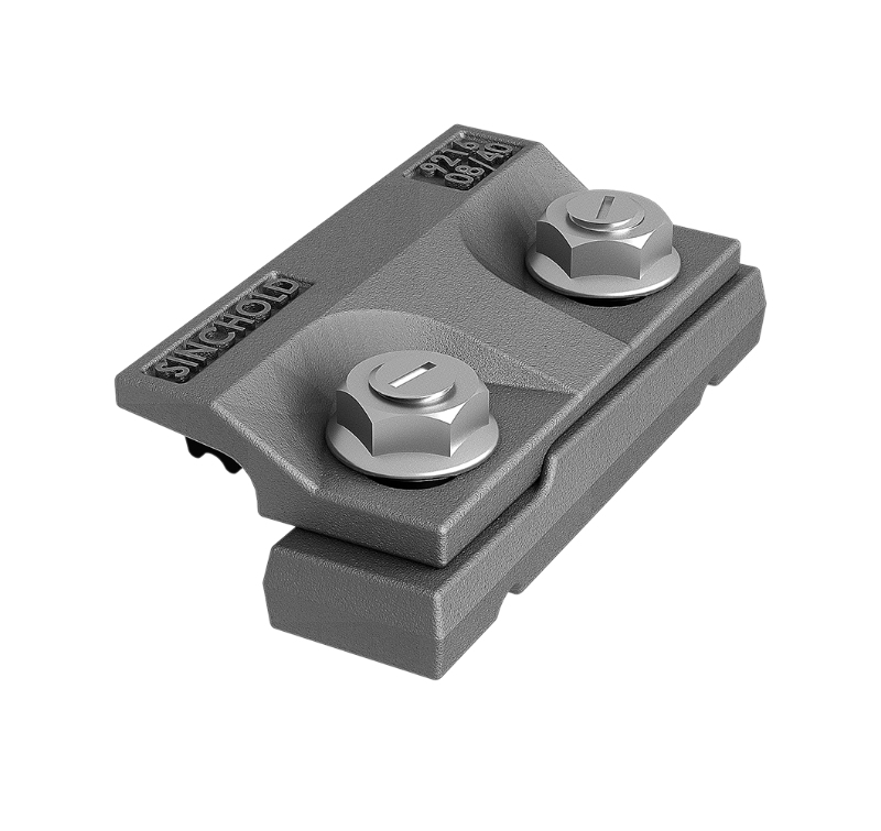
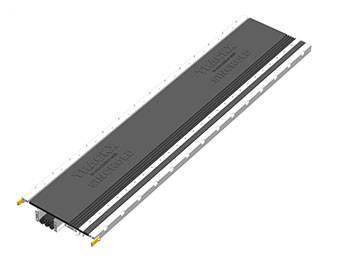
Crane rails are a critical part of material handling infrastructure in steel plants, manufacturing facilities, warehouses, ports, shipyards, and heavy industrial workshops. They provide the running surface for overhead cranes, gantry cranes, and other rail-mounted lifting equipment. Although the rail itself receives considerable attention during project planning, the support and fastening arrangement beneath it is equally important. An unsuitable support design can make rail alignment difficult, increase maintenance requirements, and complicate the transfer of wheel loads into the supporting structure.
An adjustable crane rail support system provides a practical way to position and secure crane rails while accommodating installation tolerances and project-specific alignment requirements. Depending on the design, the system may incorporate adjustable rail clamps, soleplates, steel support plates, resilient pads, bolts, grout, and other fastening components. Each part has a defined role in maintaining the intended rail position and supporting reliable crane operation.
For engineering contractors, equipment manufacturers, and industrial procurement teams, selecting a suitable system involves more than comparing individual components. Rail dimensions, wheel loads, operating conditions, supporting steelwork, concrete foundations, installation methods, and maintenance access all need to be considered together.
This article explains how adjustable crane rail support systems work, what buyers should evaluate before placing an order, and how installation and maintenance practices affect long-term performance.
What Is an Adjustable Crane Rail Support System?
An adjustable crane rail support system is an engineered arrangement used to support, position, and fasten crane rails to a structural foundation. Its primary purpose is to establish the required rail geometry and maintain that geometry under the loads and operating conditions specified for the crane installation.
The term "adjustable" generally refers to the ability to make controlled corrections to the rail position during installation. Depending on the system design, adjustments may be made through clamp geometry, slotted holes, shim arrangements, adjustable support elements, or other approved positioning mechanisms. Not every system uses the same adjustment method, so buyers should confirm the actual adjustment range and procedure with the manufacturer.
Adjustment is especially useful when a project requires accurate rail gauge, elevation, straightness, and local alignment. Fabricated support structures and concrete foundations inevitably have installation tolerances. A properly designed fastening arrangement helps installers correct permitted deviations without relying on improvised modifications.
However, adjustability does not mean that a support system can compensate for unlimited structural errors. Significant foundation settlement, insufficient beam stiffness, damaged concrete, or incorrectly positioned anchor bolts may require structural correction rather than additional adjustment at the rail fastening level.
A complete system should therefore be selected according to the project drawings, crane design requirements, and applicable engineering standards.
Main Components of an Adjustable Crane Rail Support System
The exact configuration depends on the crane type, rail profile, support structure, and operating environment. Understanding the function of each component helps buyers specify a complete and compatible assembly.
Rail Clamps
Rail clamps hold the rail in position and resist the forces that could cause unwanted movement during crane operation. Their geometry must match the specified rail profile and the intended fastening arrangement.
For adjustable crane rail support applications, clamp design is particularly important because the fastening assembly must allow the required positioning corrections while maintaining the specified restraint after final adjustment.
Procurement teams should confirm the following details:
Compatible rail profile and dimensions.
Permitted lateral adjustment range.
Clamp material and surface protection.
Bolt size, grade, and tightening requirements.
Installation clearance and tool access.
Suitability for the specified operating environment.
Clamp assemblies should not be selected by appearance alone. Two clamps that look similar may differ in their contact geometry, load-transfer characteristics, adjustment range, or compatibility with the supporting plate.
Soleplates and Steel Support Plates
Soleplates provide a defined interface between the rail fastening assembly and the underlying support structure. They can help distribute loads across the intended bearing area and provide a consistent mounting surface for fastening components.
The plate dimensions, thickness, flatness, hole arrangement, and material specification should correspond to the approved design. For projects involving fabricated steel beams, the soleplate arrangement must also be compatible with the beam geometry and the planned welding or bolting procedure.
A poorly prepared support surface can undermine the benefits of an adjustable fastening system. If a soleplate is distorted or installed at an incorrect elevation, the installer may have to make unnecessary corrections, and the final load distribution may differ from the design assumptions.
Where a project uses welded rail clips or other welded fastening components, the relationship between the clip, plate, rail, and supporting structure should be clearly defined in the installation drawings. Welding should only be performed at locations and in configurations approved by the relevant design and welding procedures.
Rubber Pads and Resilient Elements
Rubber pads may be installed between designated components to provide resilient support, accommodate specified contact conditions, or help manage vibration and noise. Their function depends on the material formulation, geometry, hardness, thickness, and intended loading.
A pad should not be treated as a universal solution for every crane rail installation. Excessive compression, incompatible materials, exposure to unsuitable chemicals, or incorrect installation can affect its service performance.
Before specifying a pad, buyers should confirm its intended position within the assembly, compression characteristics, environmental resistance, and compatibility with the rail support design. The pad must also be suitable for the loads and movements anticipated in service.
Bolts, Nuts, and Washers
Bolted connections maintain the fastening assembly in its specified configuration. Their performance depends on more than nominal diameter. Bolt grade, thread engagement, tightening method, corrosion protection, and joint design all influence the reliability of the connection.
For an adjustable assembly, installers must also understand when adjustment is permitted and when the final fastening must be secured. Tightening requirements should come from the approved installation documentation rather than an assumed torque value.
Substituting bolts with a different grade or changing the fastening arrangement without approval can alter the behavior of the connection. Procurement teams should therefore specify the required fastener standard and verify that all supplied components match the approved bill of materials.
Grout and Foundation Interfaces
Grout may be used beneath designated support plates or other components to establish continuous bearing and transfer loads to the foundation. Its role is particularly important where the installation design requires a defined bearing surface between steelwork and concrete.
The grout type, thickness, placement procedure, curing requirements, and surface preparation must follow the project specification and the selected product's technical documentation.
Grouting is not a replacement for structural design or correct support positioning. If the foundation geometry is substantially outside the permitted tolerance, the installation team should resolve the discrepancy before proceeding.
Where Are Adjustable Crane Rail Support Systems Used?
These systems are relevant to a wide range of industrial installations, but the operating conditions vary significantly between applications. A suitable solution must reflect the actual service requirements rather than relying on a generic product description.
Steel Plants and Metallurgical Facilities
Steel plants use cranes to move raw materials, semifinished products, coils, heavy equipment, and other loads. Rail installations may experience substantial wheel loads, frequent travel, repeated starts and stops, and demanding environmental conditions.
The support arrangement must be compatible with the crane's design loads, the rail profile, the supporting beams, and the site's maintenance procedures. Heat, scale, dust, and other contaminants may also influence material selection and inspection frequency.
For these projects, engineering teams should review the entire load path from the wheel and rail through the fastening assembly into the supporting structure.
Manufacturing Workshops
Overhead cranes in manufacturing facilities move components between production stations, assembly areas, and storage zones. Consistent rail alignment helps maintain the intended crane travel path and reduces the need for corrective work during installation.
An adjustable support arrangement can be useful when long runway beams require accurate positioning or when multiple rail sections must be aligned across a large workshop.
The required adjustment range should be established before installation. This allows the contractor to plan support locations, positioning equipment, measurement procedures, and final inspection activities.
Ports, Shipyards, and Container Handling Areas
Port and shipyard equipment may operate in humid, saline, or otherwise corrosive environments. Rail support components can be exposed to water, airborne salt, industrial contamination, and repeated mechanical loading.
Material selection and surface protection should reflect the actual exposure conditions. Drainage, water retention around support plates, accessibility for inspection, and the compatibility of protective coatings with installation methods should also be considered.
For these applications, corrosion resistance is not simply a purchasing specification. It is part of the maintenance strategy for the complete fastening system.
Warehouses and Logistics Facilities
Rail-mounted lifting equipment can support the movement of large components, steel products, machinery, and other materials in logistics facilities. Installation accuracy is important because runway geometry must correspond to the crane manufacturer's requirements.
For new construction, the rail support system should be coordinated with the structural steel design. For upgrades, the project team should inspect existing beams, anchor arrangements, rail condition, and available installation space before selecting replacement components.
How to Select the Right Adjustable Crane Rail Support System
A purchasing decision should begin with the application data. A supplier can only recommend a technically appropriate configuration when the key operating and structural requirements are understood.
1. Confirm the Rail Profile and Dimensions
Identify the exact rail designation, profile dimensions, and relevant dimensional tolerances. The rail profile determines the geometry of the contact and fastening arrangement.
Do not assume that a clamp designed for one rail type will fit another rail simply because the overall rail widths appear similar. Small differences in head, foot, or web geometry can affect compatibility.
If the project uses a special rail profile, provide the relevant drawing or dimensional data during the quotation stage.
2. Establish the Design Loads
The support system must be evaluated against the loads specified for the crane and its runway. Relevant inputs may include maximum wheel loads, wheel spacing, crane operating class, dynamic effects, braking forces, and applicable lateral forces.
The engineering team should determine which loads govern the rail fastening and support design. The rail clamps, plates, bolts, welds, supporting beams, and foundation interfaces should be checked as an integrated load-transfer arrangement.
Avoid selecting a system solely on the basis of crane lifting capacity. Two cranes with the same rated lifting capacity may impose different wheel loads and operating forces because of differences in crane weight, span, wheel arrangement, speed, and duty cycle.
3. Define the Required Adjustment Range
Determine how much lateral and vertical correction the installation may require, and identify the mechanism through which each correction will be made.
Some products permit limited lateral positioning, while other designs may provide additional adjustment through the supporting plate or a separate positioning arrangement. Vertical adjustment may require shims, leveling devices, or another method defined by the project design.
Ask the supplier to identify the adjustment range in measurable terms. Also confirm whether adjustment can be performed after the rail has been partially fastened and what inspection or retightening steps are required afterward.
A clearly defined adjustment range makes it easier to prepare installation procedures and avoid delays caused by unexpected alignment problems.
4. Check the Supporting Structure
The support structure may consist of reinforced concrete, structural steel beams, fabricated brackets, or another engineered foundation arrangement.
The system must be compatible with the available bearing surface, connection method, structural tolerances, and installation sequence. For existing structures, inspect corrosion, deformation, cracking, anchor condition, and evidence of settlement before deciding whether the existing support can be reused.
An adjustable fastening assembly should not be expected to correct inadequate beam stiffness or an unsuitable foundation. These issues must be addressed through structural assessment and, where necessary, remedial engineering.
5. Evaluate the Operating Environment
Environmental conditions affect the selection of steel components, fasteners, pads, protective coatings, and maintenance intervals.
Important considerations include:
Ambient temperature and temperature variation.
Moisture, salt exposure, and corrosive atmospheres.
Dust, scale, oils, and chemical contamination.
Outdoor exposure and water drainage.
Cleaning methods and access for inspection.
Compatibility of coatings with any specified welding work.
For facilities with demanding environmental conditions, request material specifications and relevant coating or corrosion-protection documentation rather than relying on general descriptions such as heavy-duty or industrial grade.
6. Consider Installation and Maintenance Access
A support system may meet the design requirements but still be difficult to install if tools cannot reach the fasteners or if adjustment points are obstructed by nearby steelwork.
Review the clearance around each fastening point, the sequence for positioning the rail, the method for measuring alignment, and the space needed for tightening and inspection.
For long runway installations, standardizing components where technically appropriate can simplify inventory management and replacement planning. However, standardization should not override differences in rail profile, loads, or support conditions.
Adjustable Crane Rail Support System Installation: A Practical Workflow
Correct installation is essential to achieving the intended performance of the system. The exact sequence varies by product and project, but the following workflow provides a useful framework for planning and quality control.
Step 1: Review Drawings and Prepare the Work Area
Before installation, verify the approved drawings, rail schedule, support locations, component specifications, and inspection requirements.
Confirm that the delivered clamps, plates, pads, bolts, and other components match the approved documentation. Check for visible deformation, damaged threads, missing parts, or coating damage.
Survey the supporting structure and record its condition. Any deviation that exceeds the specified tolerance should be reported and resolved before installation continues.
Step 2: Establish the Reference Line and Elevation
Set out the rail centerline, gauge, elevation, and relevant control points using the project-approved survey method.
The measurement procedure should account for the full runway geometry, not just isolated support locations. A rail can appear correctly positioned at one point while still developing unacceptable deviations over a longer distance.
Record the initial measurements so that installation corrections can be compared against the original survey.
Step 3: Position the Support Plates and Fastening Components
Install the designated plates and other support components according to the approved assembly drawings.
Check their orientation, seating, hole alignment, and compatibility with adjacent components. Where the design requires welded connections, confirm the specified weld locations, joint preparation, welding procedure, and inspection requirements before work begins.
Do not introduce additional welds, drill new holes, or modify clamp geometry without engineering approval.
Step 4: Place the Rail and Make Permitted Adjustments
Position the rail and install the specified fastening components. Use the designated adjustment mechanism to bring the rail into the required alignment.
Check gauge, elevation, straightness, and local positioning at the intervals established by the project specification. Make corrections systematically rather than adjusting one support in isolation without considering neighboring supports.
Temporary fastening may be appropriate during alignment, but the installation team must follow the manufacturer's sequence for final tightening and securing.
Step 5: Complete Grouting Where Required
If the design includes grouting, prepare the bearing surfaces and install the grout according to the approved procedure.
The installer should verify the specified grout material, mixing instructions, placement method, required thickness, and curing conditions. Premature loading or movement may compromise the intended bearing condition.
After curing, inspect the completed interface for visible defects and confirm that the installation meets the project's acceptance requirements.
Step 6: Perform Final Fastening and Inspection
After alignment and any required grouting have been completed, secure the fastening assembly using the specified tightening procedure.
Recheck the relevant rail geometry and inspect the connections. Confirm that the rail is supported as intended, the clamps are correctly positioned, and no unauthorized modifications have been introduced.
Any required weld inspection, dimensional survey, bolt inspection, or documented acceptance check should be completed before the system is released for operation.
Step 7: Conduct Commissioning Checks
Before the crane enters normal service, complete the inspection and testing activities required by the crane manufacturer, project specification, and applicable regulations.
Where the approved commissioning procedure calls for controlled movement or load testing, follow that procedure and record the results. Check for abnormal movement, loose connections, interference, or other observable issues.
Commissioning should not be used as a substitute for installation inspection. Defects should be identified and corrected before the equipment enters normal service.
Common Installation Problems and How to Prevent Them
Several recurring issues can increase installation time or create avoidable maintenance work. Most can be reduced through clear drawings, compatible components, and disciplined inspection.
Incorrect Clamp Selection
Using a clamp that does not match the rail profile or required adjustment range can lead to poor contact, difficult installation, or an assembly that does not meet the design intent.
Prevention: Verify the rail designation, dimensional drawing, clamp model, and fastening arrangement before ordering. For nonstandard applications, request a technical review.
Inadequate Rail Alignment
Insufficient surveying or adjustment performed without reference to the overall runway can create local deviations that become apparent during crane operation.
Prevention: Establish the survey method and acceptance tolerances before work begins. Measure the full installation at the required intervals and retain the results for handover.
Poor Bearing Conditions
Uneven support surfaces, improperly installed shims, or defective grouting may result in unintended load concentration or movement at the support interface.
Prevention: Inspect the support surface, follow the approved leveling and grouting procedure, and correct unacceptable foundation conditions rather than attempting to conceal them through improvised adjustments.
Inconsistent Fastening Practices
Uncontrolled tightening, incorrect fastener grades, or missing hardware can compromise the consistency of the assembly.
Prevention: Use the specified fasteners and tightening method. Maintain traceable inspection records where required and ensure that installers understand the difference between temporary positioning and final fastening.
Incomplete Documentation
When adjustment settings, alignment measurements, and inspection results are not recorded, future maintenance teams may have difficulty identifying changes in rail geometry or confirming the original installation condition.
Prevention: Include dimensional survey records, component identification, inspection results, and relevant installation documentation in the project handover package.
Quality Control and Inspection Requirements
Quality control should cover the complete fastening assembly rather than focusing only on the appearance of individual components.
For procurement and engineering teams, a practical inspection plan may include the following checks.
| Inspection area | What to verify | Why it matters |
|---|
| Rail compatibility | Profile, dimensions, and specified tolerances | Confirms that the fastening assembly fits the intended rail |
| Component condition | Deformation, cracks, damaged threads, and coating defects | Identifies visible defects before installation |
| Material documentation | Specified grades and relevant certificates | Supports verification against procurement requirements |
| Adjustment mechanism | Range, operation, and approved configuration | Confirms that permitted alignment corrections are available |
| Fastening connections | Bolt specifications, assembly, and tightening records | Helps establish compliance with the installation procedure |
| Rail geometry | Gauge, elevation, straightness, and other specified measurements | Verifies that the installed runway meets project tolerances |
| Grout and bearing surfaces | Material, placement, curing, and visible condition | Checks the intended support interface |
| Final documentation | Inspection records, approved deviations, and handover data | Supports future maintenance and traceability |
Acceptance criteria should come from the approved design, relevant standards, and project-specific technical specification. Generic tolerances should not be substituted for the requirements applicable to the actual crane installation.
Where required, inspection and test plans should identify the responsible parties, inspection stages, hold points, documentation, and procedures for managing nonconformities.
Maintenance of Crane Rail Support Systems
Even a correctly installed support system requires periodic inspection. The frequency and scope should reflect operating duty, environmental exposure, manufacturer guidance, and the maintenance requirements of the facility.
Inspect Fasteners and Clamps
Look for loose or missing fasteners, damaged threads, visible movement, displaced clamps, and signs of abnormal contact. Where the design requires checking tightening condition, use the specified inspection procedure rather than applying an arbitrary torque value.
Any suspected movement should be assessed in the context of the complete rail and support arrangement.
Monitor Rail Geometry
Changes in rail gauge, elevation, or straightness can indicate movement in the fastening assembly, supporting structure, or foundation.
Compare inspection measurements with the original survey and previous records. A progressive change may require investigation even if an individual measurement has not yet exceeded the specified acceptance limit.
Check Corrosion and Material Condition
Inspect exposed steel surfaces, fasteners, welded areas, and other vulnerable locations for corrosion or coating deterioration. In harsh environments, pay particular attention to areas where moisture or contaminants may accumulate.
Replacement and repair methods should be compatible with the specified materials and protective system.
Examine Grout and Support Interfaces
Where grout is used, look for visible cracking, separation, or other signs that warrant further investigation. These observations do not automatically establish a structural defect, but they may indicate a need for engineering assessment.
Similarly, unusual noise, repeated fastener loosening, or visible rail movement should be investigated rather than treated as routine maintenance issues.
Maintain Inspection Records
A useful maintenance record includes the inspection date, location, observed condition, measurements where applicable, corrective action, and follow-up requirements.
Consistent records help maintenance teams distinguish isolated defects from recurring patterns. They also provide useful evidence when planning component replacement, evaluating the condition of an existing runway, or specifying upgrades.
Adjustable Crane Rail Support Systems for New Projects and Retrofits
The selection process can differ depending on whether the system is being installed in a new facility or used to upgrade an existing crane runway.
For a new project, the rail support arrangement can be coordinated with structural steel fabrication, foundation construction, crane specifications, and installation sequencing. This coordination makes it easier to establish reference points, define tolerances, and provide suitable access for fastening and inspection.
For a retrofit, the project team must first understand the condition of the existing installation. Relevant checks may include the current rail profile, support spacing, beam condition, anchor arrangement, available adjustment range, and any evidence of previous movement or repairs.
A replacement system should not be selected solely because it fits the existing rail dimensions. The team should determine whether the existing support structure and load path remain suitable for the intended crane service.
If the crane capacity, operating duty, or runway arrangement is changing, the structural and fastening design may need to be reassessed. Existing dimensions are useful reference data, but they do not independently establish that a new configuration is adequate.
For both new construction and retrofit projects, early coordination between the crane supplier, structural engineer, installation contractor, and fastening-system manufacturer can reduce uncertainty before procurement and site work begin.
What Should Buyers Include in an RFQ?
A well-prepared request for quotation helps manufacturers evaluate the application and reduces unnecessary clarification during the purchasing process.
For an adjustable crane rail support system, buyers should provide as much of the following information as is available:
Rail type, profile, and dimensional drawing.
Crane type, rated capacity, and relevant design wheel loads.
Runway layout, rail gauge, and support spacing.
Supporting structure type and connection details.
Required lateral and vertical adjustment range.
Project design standards and dimensional tolerances.
Environmental conditions and corrosion-protection requirements.
Required materials, fastener grades, and coating specifications.
Grouting, welding, and installation requirements.
Inspection documentation, traceability, and acceptance criteria.
Estimated quantity, delivery schedule, and project location.
Requirements for technical support, installation, or maintenance.
If some information is unavailable, indicate which details are preliminary and which have been approved by the engineering team. The supplier can then identify the information needed to assess compatibility without treating assumptions as confirmed design inputs.
For projects involving several rail sections or different crane types, organize the information by rail profile, support configuration, and installation location. This makes it easier to identify where components can be standardized and where separate configurations are required.
Why Work with a Rail Fastening System Manufacturer?
Purchasing individual rail clamps and plates from separate sources can create coordination challenges if their dimensions, adjustment mechanisms, and connection details have not been checked as a complete assembly.
Working with an experienced rail fastening system manufacturer can help buyers coordinate component selection, technical documentation, production quality, and project support.
A supplier's manufacturing capabilities are only one part of the assessment. Buyers should also review whether the supplier can interpret project drawings, identify missing application data, provide clear component specifications, maintain consistent production quality, and support installation planning where required.
For international projects, communication and delivery coordination are also important. Technical queries may arise during drawing approval, fabrication, site preparation, and commissioning. A defined process for managing these queries helps prevent unauthorized changes and incomplete documentation.
The most useful supplier relationship is based on clear engineering requirements, traceable product information, realistic delivery planning, and a shared understanding of the installation scope.
Sinchold: Rail Fastening Products and Installation Support
Sinchold is an integrated manufacturer and solution provider serving the rail systems industry. Its capabilities cover research and development, design, manufacturing, and support for rail fastening systems and related infrastructure components.
The company's product range includes railway spring bars, railway turnout components, track fastening system combinations, crane rail clamps, track cleats, fish plates, bolts, coking track fixing products, and track steel products. These product categories support different rail installation requirements and should be matched to the relevant project specifications.
For buyers evaluating an adjustable crane rail support system, the first step is to define the required rail profile, support arrangement, loads, adjustment requirements, and environmental conditions. This information helps establish whether a proposed clamp or fastening configuration is suitable for the application.
Sinchold also provides rail installation and maintenance services, including rail welding and grouting. Depending on the project scope, coordination between fastening components and installation activities can help align procurement, site preparation, assembly, and inspection requirements.
The company's manufacturing facility in Nantong operates production lines under a total quality management system. In 2024, Sinchold established Sinchold KSA (SFCC) in Dammam to strengthen its presence in the Middle East and provide localized support for infrastructure projects, including service for key clients such as Saudi Aramco.
For contractors and industrial buyers, local project coordination may be useful when managing technical communication, delivery requirements, and installation schedules. Specific product availability, engineering scope, and service arrangements should be confirmed for each project.
To review relevant product options, visit Sinchold's welded rail clips product page. Buyers should provide their rail drawings and application requirements when requesting technical information, particularly where an adjustable fastening configuration must be integrated with existing structural steelwork or a new runway design.
Frequently Asked Questions
What is the main purpose of an adjustable crane rail support system?
Its main purpose is to support and secure crane rails while allowing specified positioning corrections during installation. Depending on the design, adjustment may help installers establish the required rail gauge, elevation, and alignment before final fastening.
Can an adjustable rail support system fit different crane rail profiles?
Some systems can be configured for different profiles, but compatibility should never be assumed. Rail geometry, clamp dimensions, support plates, fastening details, and design loads must be checked for each application.
Does an adjustable support system eliminate the need for accurate foundations?
No. Adjustment mechanisms accommodate only the corrections permitted by their design. Foundation defects, significant structural deviations, or inadequate beam stiffness require separate assessment and may need corrective work.
Is grouting always necessary for crane rail installation?
No. Grouting depends on the support design, foundation interface, and project specification. Where it is required, the grout type, installation procedure, and curing conditions must be defined and followed.
What information is needed to select a suitable system?
The most useful starting information includes the rail profile, crane wheel loads, runway layout, support structure, required adjustment range, environmental conditions, and applicable technical standards. Drawings and project specifications help the manufacturer assess compatibility.
Can welded rail clips be used in an adjustable support arrangement?
That depends on the specific product design and installation method. Welding may form part of a fastening configuration, but the permitted adjustment mechanism and welding locations must be confirmed in the approved drawings. Unapproved welding or modification can compromise the intended arrangement.
How often should crane rail supports be inspected?
There is no universal inspection interval suitable for every installation. The maintenance schedule should follow the crane manufacturer's recommendations, applicable regulations, operating conditions, and the facility's risk-based maintenance program. More demanding service or harsh environmental exposure may require closer monitoring.
Conclusion
An adjustable crane rail support system should be selected as part of the complete crane runway design, not as an isolated fastening accessory. Rail compatibility, wheel loads, support geometry, adjustment range, fastening details, environmental exposure, and installation procedures all influence the suitability of the final assembly.
For B2B buyers, the most effective procurement process begins with accurate application data and clear technical documentation. Coordinating the rail clamps, support plates, resilient elements, bolts, grout, and installation requirements before ordering helps reduce compatibility issues and makes inspection easier.
Sinchold offers a range of rail fastening products and related installation services for industrial rail applications. By providing the rail profile, project drawings, operating conditions, and required adjustment parameters, buyers can begin a more focused technical discussion about the appropriate support and fastening configuration for their crane runway.
 中文
 English
 Россия
 Deutsch
 Français
 Español
 Português
 العربية


 Sinchold
 Oct 20 2026
 Sinchold


 Recommended news