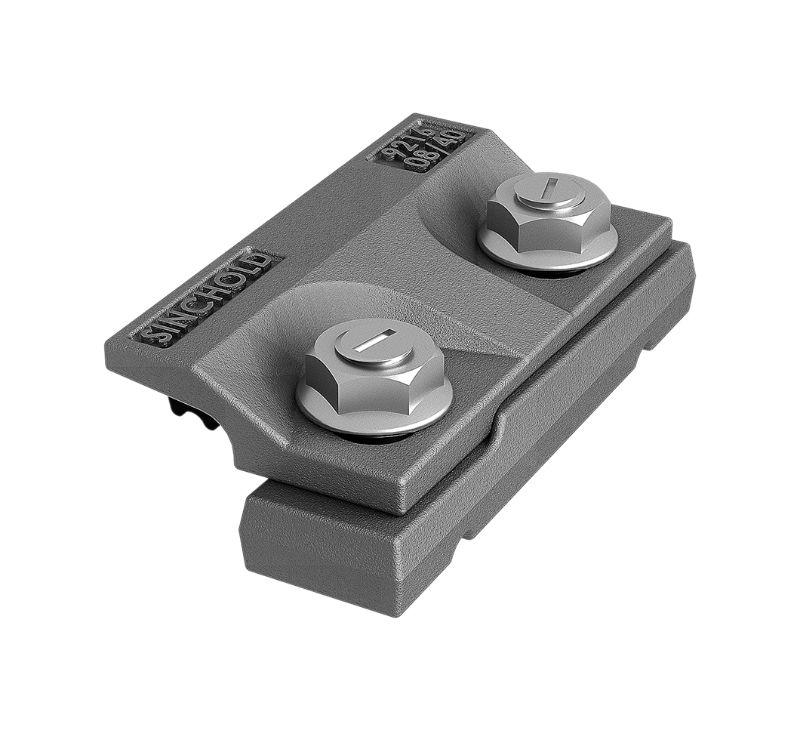
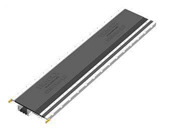
Container terminals depend on rail-mounted equipment to move containers efficiently between vessels, storage yards, trucks, and rail transport. Ship-to-shore cranes, rail-mounted gantry cranes, and other heavy handling equipment can operate for long hours under high wheel loads, repeated acceleration and braking, and demanding environmental conditions. In this environment, the rail system is not simply a steel rail fixed to concrete. It is a complete load-transfer and positioning system that must maintain rail alignment, resist lateral and longitudinal forces, accommodate thermal movement, and remain serviceable throughout the operating life of the terminal.
A properly engineered Container Terminal Crane Rail System combines crane rails, rail clips or clamps, soleplates, rubber pads, bolts, grouting materials, supporting structures, adjustment components, and installation methods. The performance of the complete assembly depends on how these components work together. A rail with excellent material properties can still experience premature problems if the supporting surface is uneven, the fastening system is incorrectly selected, or drainage and corrosion protection are overlooked.
For terminal owners, EPC contractors, crane manufacturers, engineering consultants, and maintenance teams, the key question is therefore not simply which crane rail to purchase. The more important question is how to build a rail fastening and support system that can maintain the required geometry under real operating conditions.
Sinchold provides integrated rail system solutions covering R&D, design, manufacturing, installation, and maintenance. Its product range includes rail fastening systems, rail clamps, soleplates, rubber pads, steel rails, bolts, grouting materials, and related rail components. Its settlement-resistant track system is also designed around a practical maintenance issue found in heavy-duty track applications: localized foundation settlement and the resulting change in rail elevation.
Why Crane Rail Systems Are Critical in Container Terminals
Container handling equipment operates differently from conventional railway vehicles. A railway track generally supports vehicles that travel along a defined route, while a crane rail system supports equipment whose wheels, loads, and operating cycles are concentrated over relatively short sections of track.
A rail-mounted gantry crane, for example, may repeatedly accelerate, stop, reverse, and traverse while carrying containers with significant dynamic loads. Ship-to-shore cranes are subject to additional operational forces generated by trolley movement, wind, lifting operations, braking, and structural movement.
These operating conditions place several demands on the rail system:
High vertical wheel loads must be transferred safely into the foundation.
Lateral forces must be controlled without damaging the fastening assembly.
Longitudinal forces from braking and acceleration must be transferred into the supporting structure.
Rail gauge and alignment must remain within the specified operating tolerances.
The rail must remain securely restrained while allowing the movement required by the design.
Contact between steel components and concrete must be managed to reduce local damage.
Water, salt, chemicals, and other environmental factors must not cause premature deterioration.
Maintenance activities should be possible without unnecessarily disrupting terminal operations.
This makes the fastening system an important part of the overall crane track design rather than an accessory added after the rail has been selected.
The supporting structure may be a reinforced concrete beam, concrete slab, steel structure, embedded track structure, or another engineered foundation. Regardless of the structural configuration, the interface between rail and foundation requires careful attention.
A reliable system should provide a predictable load path:
Crane wheel → rail → fastening/soleplate assembly → pad and supporting interface → foundation
Every interface in this load path can influence the service performance of the track.
What Is a Container Terminal Crane Rail System?
A Container Terminal Crane Rail System is an engineered track assembly used to support and guide rail-mounted container-handling equipment. Depending on the application, it may include crane rail sections, rail clips, welded or bolted rail fastening components, soleplates, rubber or elastomeric pads, adjustment plates, bolts, anchors, grout, and associated installation hardware.
The exact configuration depends on the crane type, rail profile, wheel loads, foundation design, operating environment, required tolerances, and project specifications.
For procurement purposes, it is useful to divide the system into several functional layers.
Rail
The rail provides the running surface for the crane wheels and transfers concentrated wheel loads into the fastening assembly. Rail selection should consider wheel load, rail head dimensions, wheel compatibility, bending behavior, wear, and the expected operating cycle.
Common crane rail profiles include A-series and QU-series rails, although the appropriate profile must be determined from the engineering requirements rather than selected simply because it is commonly used.
For example, Sinchold's settlement-resistant track system product range includes A100, QU80, QU100, and QU120 crane rail configurations. The appropriate rail should always be matched to the crane manufacturer's requirements and the project design rather than selected from a general catalog.
Soleplate
A soleplate provides a stable interface between the rail fastening arrangement and the supporting structure. It can help distribute loads, maintain the required rail position, and create a controlled interface for fastening components.
In heavy-duty crane applications, the soleplate design needs to account for:
Load distribution
Fastener positioning
Rail adjustment
Corrosion protection
Dimensional tolerances
Installation sequence
Foundation conditions
The soleplate should be considered as part of the complete fastening assembly rather than as an isolated steel plate.
Rail Clips and Clamps
Rail clips or clamps restrain the rail while allowing the fastening system to perform according to its design.
Different applications may require bolted rail clips, welded rail clips, adjustable clamps, or specialized crane rail clamps. The selection depends on the rail profile, foundation arrangement, expected loads, installation method, and required adjustment capability.
The fastening assembly must provide sufficient restraint without introducing undesirable stress concentrations into the rail.
Rubber or Elastomeric Pads
A resilient pad can be installed between the rail or soleplate and its supporting surface depending on the system configuration.
The pad may help:
Distribute contact pressure
Reduce local stress concentrations
Provide resilience at the rail-support interface
Accommodate minor surface irregularities
Reduce vibration transmission
Protect steel and concrete interfaces
However, a rubber pad should not be selected solely by hardness or thickness. Its mechanical properties, compression behavior, environmental resistance, dimensional stability, and compatibility with the complete fastening arrangement all need to be considered.
Bolts and Anchoring Components
Bolts transfer clamping forces through the fastening assembly. Their diameter, grade, coating, tightening method, embedment, and installation tolerance must be compatible with the system design.
In a container terminal, corrosion protection is particularly important because the track can be exposed to rain, humidity, salt-laden air, washdown water, and industrial contaminants.
Grouting
Grouting is often used to fill voids and establish a controlled interface between track components and the supporting foundation.
Poorly executed grouting can undermine an otherwise well-designed track system. Voids, inadequate surface preparation, incorrect mixing, poor flow, insufficient curing, or unsuitable material selection can result in uneven load transfer and localized deterioration.
For this reason, grouting should be treated as an engineering and installation activity rather than a simple finishing operation.
Main Loads Acting on a Crane Rail Track
Understanding the loads acting on the rail system is essential when selecting components.
Vertical Wheel Loads
The most obvious load is the vertical load generated by the crane wheels. This includes the self-weight of the crane, lifted loads, and dynamic effects.
The design load is not necessarily equal to the static wheel load. Operational acceleration, braking, lifting, trolley movement, uneven rail geometry, and other dynamic effects can influence the actual forces transmitted into the rail system.
For procurement teams, this means the rail and fastening system should be evaluated against the project's design wheel loads rather than only the crane's total rated lifting capacity.
Lateral Forces
Lateral forces may arise from crane travel, wheel and rail interaction, skewing, wind, structural movement, and differences in wheel or rail geometry.
If the rail fastening system cannot maintain the required lateral restraint, repeated movement can contribute to:
The fastening system therefore needs sufficient lateral restraint while remaining compatible with the required rail adjustment and thermal movement.
Longitudinal Forces
Acceleration and braking produce longitudinal forces along the rail.
These forces are particularly relevant for automated or high-cycle crane operations because the same track sections can experience repeated loading over many operating cycles.
The complete track system must provide an appropriate load path for these forces. Rail clips, anchors, soleplates, bolts, and supporting structures should be considered together.
Thermal Movement
Long crane tracks can experience significant temperature variation. Steel rail expands and contracts with changes in temperature.
The rail fastening design therefore needs to distinguish between:
Simply increasing clamping force does not automatically create a better track. Excessive restraint or an unsuitable fastening arrangement can introduce additional stress into the system.
Thermal behavior should be evaluated as part of the complete track design.
Rail Alignment Is a System Requirement
Crane wheels depend on the rail geometry for smooth and predictable travel. Even when the rail itself is manufactured correctly, the finished track can develop alignment problems because of installation tolerances, foundation movement, differential settlement, thermal effects, or component wear.
Important geometric parameters may include:
The required tolerances should come from the crane manufacturer, project specifications, applicable standards, and engineering calculations.
A fastening system with adjustment capability can provide a useful maintenance advantage. Instead of correcting every localized elevation problem by removing and reinstalling the rail, an adjustable system can allow controlled correction at the fastening interface.
This approach becomes particularly relevant where the foundation itself may undergo localized settlement.
Why Foundation Settlement Creates a Maintenance Problem
Foundation settlement is not necessarily uniform.
A long crane runway can contain sections supported by different soil conditions, structural elements, drainage arrangements, or construction stages. One portion may remain stable while another experiences a localized change in elevation.
When this occurs, the rail follows the supporting structure unless the track system provides a means of adjustment.
A small change in rail elevation can become operationally significant because crane wheels interact with the track continuously. A local depression can change wheel loading, create additional dynamic effects, and affect crane travel.
Traditional correction methods may require:
Identifying the affected section
Stopping or restricting crane operation
Removing fastening components
Lifting or repositioning the rail
Adding or replacing support material
Reinstalling and tightening fasteners
Rechecking rail geometry
Returning the crane to service
The actual procedure depends on the track design, but the common issue is that correction can be labor-intensive and disruptive.
How a Settlement-Resistant Track System Works
A settlement-resistant track system addresses this issue by incorporating adjustment into the fastening arrangement.
Sinchold describes its Settlement-Resistant Track System as a fixed-track solution designed to compensate for track foundation settlement through an adjustment mechanism. The system uses height-adjustment components, such as upper adjustment plates or shims, to restore rail elevation after localized settlement.
The engineering concept is straightforward.
When the foundation remains at its designed elevation, the fastening assembly holds the rail at the specified level.
If localized settlement occurs, the rail elevation can be corrected by adjusting the designated components in the fastening assembly rather than reconstructing the entire track section.
This does not eliminate foundation settlement. Instead, it provides a controlled method of managing its effect on rail geometry.
That distinction is important.
A settlement-resistant system should not be marketed as a replacement for adequate civil engineering and foundation design. It is better understood as a track maintenance and adjustment strategy that can make the rail system more adaptable when localized movement occurs.
Where Adjustable Rail Systems Can Add Value
Adjustability can be particularly useful in facilities where equipment availability is closely linked to production.
Container terminals typically operate around vessel schedules, yard movements, gate operations, and intermodal connections. Extended crane downtime can affect more than one piece of equipment.
An adjustable fastening system can potentially reduce the amount of dismantling required during localized rail-level correction.
The practical benefits may include:
Faster correction of localized rail elevation
Reduced dismantling of track components
Lower maintenance labor requirements
Better control over rail geometry
Reduced disruption to crane operation
Easier future adjustment
Improved maintainability of long crane tracks
Sinchold's published information specifically positions its settlement-resistant system for heavy-duty environments where maintenance without extended production interruption is important.
Whether these advantages can be achieved on a specific project depends on the actual system configuration, adjustment range, installation quality, settlement characteristics, and maintenance procedures.
Selecting the Right Crane Rail Profile
Rail selection should begin with engineering requirements rather than product availability.
A procurement specification for a container terminal crane rail should typically identify:
Crane type
Maximum wheel load
Wheel diameter
Wheel material
Wheel spacing
Number of wheels
Crane operating speed
Acceleration and braking characteristics
Rail span
Support spacing
Environmental conditions
Rail fastening arrangement
Required service life
Applicable standards
Rail geometry requirements
A larger rail profile is not automatically the correct solution.
An oversized rail may increase material and structural requirements without providing meaningful operational benefits. An undersized rail can create excessive stress, deformation, or wear.
The rail should therefore be selected through a combination of structural analysis, wheel-rail compatibility, fastening design, and project specifications.
Rail and Wheel Compatibility
Rail design cannot be separated from crane wheel design.
The contact between the wheel and rail determines how loads are transferred. Wheel diameter, tread geometry, flange dimensions, material hardness, and contact stresses can all influence rail performance.
When selecting a Container Terminal Crane Rail System, the engineering team should obtain wheel information from the crane manufacturer wherever possible.
Important questions include:
What is the wheel diameter?
What is the wheel tread width?
What wheel material is being used?
What is the maximum wheel load?
What is the expected wheel load distribution?
What is the wheel flange geometry?
What is the operating speed?
What is the expected wheel replacement interval?
These factors help determine whether a particular rail profile and fastening arrangement are appropriate.
Corrosion Protection in Container Terminal Environments
Corrosion is an important consideration for rail fastening systems installed in coastal and industrial environments.
Container terminals are often exposed to:
Marine air
Salt spray
Rain
High humidity
Standing water
Cleaning chemicals
Industrial contaminants
Temperature cycling
The corrosion risk is not limited to the rail itself. Clips, clamps, bolts, soleplates, adjustment components, anchors, and other steel parts can also be affected.
A corrosion protection strategy may include appropriate material selection, protective coatings, drainage design, surface treatment, sealing, inspection, and replacement procedures.
Sinchold's settlement-resistant track system information identifies corrosion resistance, waterproofing, and moisture resistance as design considerations intended to support long service life.
For project procurement, however, generic descriptions such as "corrosion resistant" should not replace a technical specification. The buyer should request details of the material, coating system, applicable standards, coating thickness where relevant, environmental classification, and expected maintenance requirements.
Water Management and Drainage
Water is often underestimated when designing crane rail systems.
A fastening assembly may be mechanically sound but still experience premature deterioration if water repeatedly accumulates around steel components or penetrates interfaces.
Poor drainage can contribute to:
Corrosion
Freeze-thaw damage in cold climates
Concrete deterioration
Grout degradation
Accumulation of contaminants
Fastener deterioration
Loss of interface performance
The track system should therefore be considered together with the civil drainage arrangement.
A good rail system cannot compensate indefinitely for a foundation that consistently holds water.
During project design, engineers should examine drainage slopes, drainage channels, surface sealing, water paths, low points, and access for cleaning and inspection.
The Role of Rubber Pads
Rubber pads are widely used in rail fastening systems, but their function should be defined precisely.
Depending on the system, the pad may provide a resilient interface, distribute pressure, reduce vibration transmission, accommodate small surface irregularities, or protect contacting surfaces.
The pad must be selected for the actual loading and environment.
Relevant technical properties can include:
Compression behavior
Compression set
Hardness
Tensile strength
Elongation
Fatigue resistance
Temperature resistance
Oil resistance
Water resistance
Chemical resistance
Aging characteristics
A pad that performs well in a laboratory under one loading condition may not provide the same performance after years of repeated crane loading and environmental exposure.
For B2B procurement, the correct approach is to request the relevant technical data and confirm that the pad is compatible with the complete rail fastening assembly.
Grouting: The Interface Between Design and Construction
Grouting is one of the areas where field workmanship can strongly influence final track performance.
Even if rail, clips, soleplates, and bolts are manufactured accurately, the supporting interface may not perform as intended if the grout installation is inconsistent.
Before grouting, the installation team should verify:
The selected grout should have mechanical and environmental properties appropriate for the actual application.
The objective is not simply to fill space beneath the rail assembly. The objective is to create a stable and predictable interface that transfers loads as intended.
Installation of a Container Terminal Crane Rail System
Installation quality directly affects track performance.
A typical installation workflow may include several stages.
1. Foundation Inspection
Before installing the rail assembly, the foundation should be surveyed.
The team should check:
Any significant deviation should be documented before the track components are installed.
2. Positioning of Soleplates
Soleplates or base components should be positioned according to the engineering drawings.
The installation team should verify centerline, spacing, orientation, and elevation.
3. Installation of Pads and Fasteners
Pads, clips, clamps, bolts, and other components should be installed according to the approved assembly procedure.
Fasteners should not simply be tightened by visual judgment when the design specifies a defined torque or tension.
4. Rail Placement
The rail is then positioned according to the specified track geometry.
At this stage, alignment should be checked rather than assumed.
5. Rail Alignment and Leveling
Rail elevation, gauge, straightness, and alignment should be surveyed using suitable instruments.
For long crane tracks, the measurement method should be established before installation so that the results can be compared consistently during maintenance.
6. Grouting
Where grout is part of the design, the grout should be installed under controlled conditions.
Voids and incomplete filling should be avoided.
7. Fastener Tightening
Fasteners should be tightened according to the approved procedure.
The sequence can matter because uneven tightening may affect rail position.
8. Final Survey
After installation, the complete rail system should be inspected and surveyed.
Any deviation should be corrected before the crane enters normal operation.
Rail Welding and Joint Considerations
Long crane tracks often require careful treatment of rail joints.
The selected joint configuration depends on the project design and rail system. Where rail welding is specified, welding procedures, rail preparation, alignment, temperature conditions, inspection, and finishing all need to be controlled.
Poor rail joints can become localized sources of:
Impact loading
Wheel wear
Noise
Vibration
Rail head damage
Fastener stress
Maintenance requirements
Rail welding should therefore be treated as a specialized construction activity rather than simply connecting two pieces of steel.
Sinchold identifies rail welding and rail installation among its rail-system services and describes itself as an integrated provider covering rail-system design, production, installation, and maintenance.
Maintenance Planning Should Start During Design
Maintenance is often considered after construction, but this can create unnecessary limitations.
A better approach is to evaluate maintainability during the design stage.
For a crane rail system, engineers should ask:
How will rail alignment be checked?
How can localized settlement be corrected?
Can fasteners be accessed safely?
Can damaged pads be replaced?
How are corroded components inspected?
Can individual components be replaced without dismantling the entire assembly?
What equipment is required for rail adjustment?
How long does a typical corrective maintenance operation take?
Can maintenance be performed during planned crane downtime?
These questions can influence the selection of the fastening system just as much as the initial installation cost.
A component that costs slightly more but can be adjusted or replaced without extensive dismantling may have a lower lifecycle cost.
Inspection Points for Existing Crane Rail Systems
Routine inspection should focus on both visible component condition and track geometry.
Rail Inspection
Inspect for:
Fastener Inspection
Check for:
Loose bolts
Broken clips
Deformation
Corrosion
Missing components
Loss of clamping force
Abnormal movement
Pad Inspection
Look for:
Permanent deformation
Cracking
Extrusion
Hardening
Chemical deterioration
Uneven compression
Foundation and Grout Inspection
Check for:
Cracking
Voids
Separation
Water accumulation
Concrete deterioration
Local settlement
Geometry Inspection
Measure:
Rail elevation
Gauge
Horizontal alignment
Longitudinal level
Local deviations
The inspection frequency should be based on the crane operating cycle, environmental conditions, manufacturer recommendations, project specifications, and observed track behavior.
Signs That a Crane Rail System Needs Attention
Maintenance teams should investigate changes in crane operation rather than waiting for visible structural damage.
Potential warning signs include:
Increased crane vibration
Abnormal wheel noise
Repeated fastener loosening
Visible rail movement
Uneven wheel contact
Localized rail wear
Increasing alignment deviations
Water accumulation
Cracked grout
Repeated correction of the same track section
A recurring problem at the same location can be particularly informative.
If a section repeatedly requires elevation correction, the issue may be related to foundation movement rather than simply a defective fastening component.
In that situation, replacing fasteners without investigating the underlying cause may only provide a temporary solution.
Conventional Fixed Track Versus Adjustable Track
The decision between a conventional fixed fastening arrangement and an adjustable or settlement-resistant system should be based on the project conditions.
A conventional fixed system may be appropriate where:
The foundation is stable
Settlement risk is low
Track geometry can be maintained through standard methods
Maintenance access is straightforward
Project conditions are well controlled
An adjustable system may offer additional value where:
Differential settlement is possible
The track is installed over variable ground conditions
Rail geometry is highly sensitive
Crane downtime is costly
Future adjustment is expected
Maintenance access is limited
The track is part of a high-duty-cycle operation
The correct solution depends on engineering analysis rather than the assumption that one fastening concept is universally better.
Reducing Total Cost of Ownership
B2B buyers often compare rail systems using initial purchase price. This is understandable, but it can overlook the largest costs associated with crane track problems.
Lifecycle cost can include:
Initial material cost + installation cost + inspection cost + maintenance labor + replacement components + equipment downtime + corrective civil work
A fastening system with a lower purchase price may become more expensive if it requires frequent adjustment, difficult component replacement, or long equipment shutdowns.
Conversely, an adjustable system may justify a higher initial investment when it significantly simplifies future maintenance.
For a container terminal, the economic value of maintenance time should be evaluated carefully.
If a crane is a critical part of a vessel-handling process, even a relatively short interruption can have consequences beyond the direct cost of the maintenance crew.
How to Specify a Crane Rail System for Procurement
A clear technical inquiry helps suppliers provide a more accurate solution.
Instead of sending only the rail size and project quantity, procurement teams should provide as much of the following information as possible:
Project Information
Crane Information
Crane type
Manufacturer
Maximum wheel load
Wheel diameter
Wheel spacing
Number of wheels
Operating speed
Acceleration
Braking conditions
Duty cycle
Rail Information
Fastening Information
Installation Information
This information enables the supplier and engineering team to determine whether a standard system can be used or whether a customized configuration is required.
Questions to Ask a Crane Rail System Supplier
Before placing an order, buyers should request technical documentation rather than relying only on product photographs or general descriptions.
Useful questions include:
Which crane rail profiles are supported?
What maximum wheel loads can the fastening system accommodate?
What are the allowable rail adjustment ranges?
How is lateral restraint achieved?
How is longitudinal force transferred?
What pad material is used?
What corrosion protection is applied?
What fastener grade and coating are specified?
What installation tolerances are required?
Is grouting part of the recommended installation?
How is rail elevation corrected after foundation settlement?
Can individual components be replaced?
What inspection procedures are recommended?
What technical drawings are available?
Can the supplier support installation and commissioning?
Can the system be adapted to existing rail foundations?
What documentation is supplied for quality control?
What project references are available for comparable applications?
These questions help distinguish a component supplier from an integrated rail-system provider.
Why Integrated Rail Engineering Can Simplify Projects
A crane rail system involves multiple components that must work together.
If the rail comes from one supplier, clamps from another, pads from a third, and installation is handled by a separate contractor, responsibility for interface problems can become unclear.
An integrated supplier can potentially coordinate:
Rail selection
Fastening design
Soleplate design
Pad selection
Bolt specifications
Grouting
Rail welding
Installation
Alignment
Maintenance
This does not eliminate the need for independent engineering review or project-specific calculations. It can, however, reduce the number of interfaces that need to be coordinated by the EPC contractor.
For large infrastructure projects, clear responsibility for the track assembly can be valuable.
Sinchold as an Integrated Rail System Supplier
Sinchold operates as an integrated manufacturer and solution provider for rail systems, with capabilities covering research and development, design, manufacturing, installation, and maintenance.
Its product portfolio includes rail fastening components, rail clips, soleplates, rubber pads, steel rails, bolts, grouting products, rail installation services, and related track components.
The company operates a production facility in Nantong and uses a total quality management approach for its manufacturing activities. Sinchold also established Sinchold KSA in Dammam to strengthen its support capabilities in the Middle East and provide more localized service for infrastructure projects.
This integrated model is relevant to container terminal projects because crane rail performance depends on the interaction between multiple components and construction activities.
The company describes its settlement-resistant track system as an adjustable solution for situations where foundation settlement affects rail elevation. The system is designed to use adjustment components to restore track level without necessarily dismantling the complete track assembly.
For a project requiring a Container Terminal Crane Rail System, the practical value of this approach should be assessed against the project's foundation conditions, crane operating profile, allowable rail tolerances, and maintenance strategy.
Applications Beyond Container Terminals
Although container terminals are an important application, heavy-duty crane rail systems are also used in other industries.
Potential applications include:
Steel plants
Metallurgical facilities
Shipyards
Heavy manufacturing
Power plants
Bulk material handling facilities
Ports and wharves
Automated industrial facilities
Coking plants
Mining-related infrastructure
Each application has different loading and environmental requirements.
A steel plant may expose components to high temperatures and scale. A port may present salt and moisture exposure. A coking facility may involve chemical contamination and elevated temperatures. An automated warehouse may place greater emphasis on dimensional accuracy and repeatable positioning.
The fastening system should therefore be selected according to the application rather than assuming that a single standard configuration is appropriate everywhere.
Design Considerations for New Container Terminals
For a new terminal, crane rail design should be integrated into the overall civil and mechanical design process.
The engineering sequence should ideally include:
Crane specification
Wheel load calculation
Rail selection
Track structural design
Fastening system selection
Foundation design
Drainage design
Rail alignment requirements
Installation methodology
Survey and quality-control plan
Maintenance strategy
This approach helps avoid a common procurement problem: selecting rail and fasteners before the final loading and foundation conditions are established.
The track system should instead be developed as part of the crane runway.
Considerations for Existing Terminal Upgrades
Retrofit projects present different challenges.
An existing terminal may already have:
Before replacing components, the engineering team should survey the existing system.
A retrofit may involve replacing only the fastening system, correcting rail alignment, improving drainage, replacing damaged pads, repairing grout, or introducing an adjustable fastening concept.
In some cases, the existing rail can remain while the support and fastening arrangement is upgraded. In other cases, rail replacement may be necessary.
The correct approach depends on inspection results.
Avoiding Common Procurement Mistakes
Several procurement mistakes can create problems later.
Choosing by Rail Weight Alone
Rail weight is important, but it does not define the performance of the complete track system.
Ignoring Foundation Conditions
A fastening system cannot compensate for every foundation problem. Settlement risk should be assessed before system selection.
Treating Clips as Standard Hardware
Clips and clamps are load-bearing components. Their geometry, material, clamping behavior, and compatibility with the rail matter.
Selecting Pads Only by Thickness
Pad performance depends on mechanical and environmental properties, not just dimensions.
Leaving Grouting to the Final Construction Stage
Grout requirements should be integrated into the track design and installation method from the beginning.
Focusing Only on Initial Price
Lifecycle maintenance and crane downtime can have a significant economic impact.
Not Planning for Future Adjustment
If the foundation has a foreseeable settlement risk, adjustment capability should be considered during initial design rather than added after problems occur.
Quality Control During Manufacturing
For a rail fastening supplier, manufacturing quality affects field performance.
Quality control should address dimensions, material properties, surface treatment, weld quality where applicable, fastener characteristics, and assembly consistency.
For customized fastening systems, dimensional control becomes particularly important because multiple components must interface correctly.
A supplier should be able to provide appropriate technical documentation, inspection records, material information, and drawings according to project requirements.
For major infrastructure projects, buyers may also require inspection plans, quality-control procedures, factory inspection, sample approval, or third-party testing.
The exact documentation package should be established during procurement rather than after production begins.
Documentation Required for B2B Projects
A professional rail system supplier should be prepared to provide technical information appropriate to the project.
Depending on the scope, this may include:
For an international project, documentation may also need to support customs, project approval, site installation, and local regulatory requirements.
Good documentation reduces ambiguity between the supplier, EPC contractor, installation team, and terminal operator.
Maintenance Strategy for Long Rail Tracks
Long crane runways should be divided into manageable inspection sections.
Each section can be assigned identification numbers so that maintenance teams can track:
Rail elevation
Alignment measurements
Fastener condition
Grout condition
Pad condition
Settlement history
Repair history
This creates a useful maintenance record.
If the same location repeatedly requires adjustment, the historical data can help engineers determine whether the issue is progressing.
For an adjustable fastening system, the adjustment history can also indicate how much available adjustment capacity remains.
This is a more useful maintenance strategy than waiting for a crane operator to report abnormal movement.
The Importance of Maintenance Access
Track design should consider how technicians will reach the fastening components.
A system may be technically adjustable but practically difficult to maintain if access is obstructed by structural elements, cable trays, drainage channels, or other equipment.
Maintenance access should therefore be reviewed during design.
Consider:
For active terminals, maintenance planning should also consider whether work can be performed during short operational windows.
Building a Reliable Long-Term Track Strategy
A reliable crane rail system is the result of several factors working together:
Correct engineering + suitable components + controlled installation + accurate alignment + effective drainage + planned inspection + maintainability
No individual component can compensate for a fundamentally unsuitable system design.
A high-quality rail installed on a poorly prepared foundation can still develop problems.
Likewise, an excellent fastening assembly can underperform if the rail is incorrectly aligned or the fasteners are improperly installed.
The most reliable projects therefore treat the rail system as a complete engineered assembly.
Final Checklist for Container Terminal Crane Rail Projects
Before finalizing a crane rail system, project teams should confirm the following.
Engineering
Crane wheel loads have been confirmed.
Rail profile has been selected based on actual loading.
Rail-wheel compatibility has been reviewed.
Lateral and longitudinal forces have been considered.
Thermal movement has been evaluated.
Foundation conditions have been assessed.
Settlement risk has been considered.
Required rail tolerances have been defined.
Components
Rail specification is confirmed.
Clips or clamps are compatible with the rail.
Soleplates are suitable for the foundation.
Pads meet the required mechanical properties.
Bolts and anchors meet project requirements.
Corrosion protection is appropriate.
Adjustment components are defined where required.
Grouting material is compatible with the installation.
Installation
Foundation survey has been completed.
Rail alignment procedure is established.
Fastener installation procedure is approved.
Welding requirements are defined.
Grouting procedure is available.
Final geometry inspection is planned.
Installation records will be maintained.
Maintenance
Inspection intervals are defined.
Rail geometry can be monitored.
Fasteners can be accessed.
Damaged components can be replaced.
Settlement correction procedures are available.
Spare parts can be supplied.
Maintenance history can be recorded.
Conclusion
A Container Terminal Crane Rail System should be evaluated as a complete engineering solution rather than a collection of individual rail components. Rail profile, clamps, soleplates, pads, bolts, grouting, foundation conditions, alignment, drainage, installation, and maintenance all influence the performance of the final track.
For container terminals, the most important design objective is not simply to install a rail that can carry the crane. The track must continue to provide accurate and predictable support under repeated wheel loads, acceleration, braking, environmental exposure, and long-term foundation movement.
Settlement is a particularly important consideration for long crane runways. Where localized foundation movement is possible, an adjustable or settlement-resistant fastening system can provide an additional method for maintaining rail elevation and reducing the amount of dismantling required during corrective maintenance. Sinchold's settlement-resistant track system uses adjustable components to address this specific maintenance challenge, while its broader product range covers rails, rail clips, soleplates, rubber pads, bolts, grouting, and related rail-system products.
For project owners and B2B buyers, the best procurement approach is to start with the actual operating conditions: crane wheel loads, rail geometry, foundation design, environment, duty cycle, maintenance access, and expected service life. Once these requirements are established, the rail and fastening system can be selected as an integrated solution.
Sinchold supports rail-system projects with manufacturing, design, installation, and maintenance capabilities. For a new container terminal, crane runway upgrade, or heavy-duty industrial rail application, buyers can provide the rail profile, crane parameters, track layout, foundation details, and project requirements to develop a suitable fastening and support configuration.
The goal is straightforward: maintain rail geometry, transfer loads reliably, simplify maintenance, and keep rail-mounted equipment operating safely and efficiently over the intended service life.
 中文
 English
 Россия
 Deutsch
 Français
 Español
 Português
 العربية


 Sinchold
 Oct 08 2026
 Sinchold


 Previous News

 Recommended news