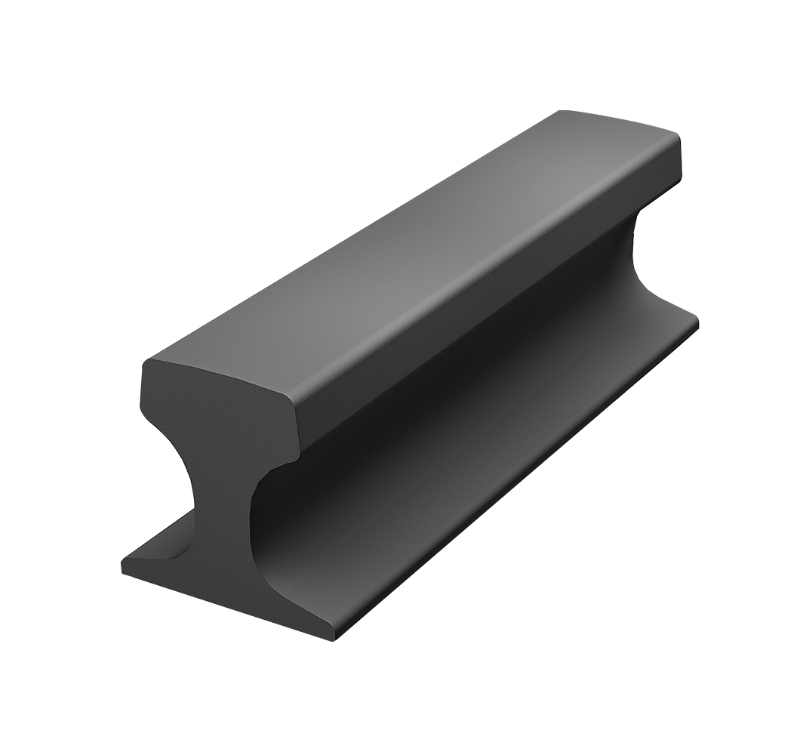
Gantry cranes operate under demanding conditions in container terminals, shipyards, steel plants, fabrication workshops, precast concrete yards, and heavy industrial facilities. Their rail systems must support repeated wheel loads, resist lateral forces, maintain alignment, and accommodate the effects of temperature changes and structural movement. A reliable gantry crane rail fastening system is essential for keeping the crane running smoothly and reducing the risk of premature rail wear, loose fasteners, and unplanned maintenance.
Selecting the right fastening components requires more than matching a rail profile to a clamp. Engineers and procurement teams need to consider crane wheel loads, rail section geometry, supporting steelwork or concrete foundations, operating speed, environmental exposure, installation tolerances, and long-term maintenance requirements. Each factor affects how the rail transfers forces to the supporting structure and how the complete system performs under repeated operation.
For industrial buyers, a well-designed fastening arrangement should provide sufficient restraint without unnecessarily restricting rail movement, allow practical installation and adjustment, and remain accessible for inspection and replacement. These requirements become especially important in facilities where cranes handle heavy materials continuously or where production interruptions carry significant operational costs.
This guide explains the main components of a gantry crane rail fastening system, how to evaluate different fastening options, what to check during installation, and how to establish a maintenance plan. It is intended for crane manufacturers, engineering contractors, infrastructure developers, plant operators, and purchasing teams sourcing rail fastening components for new projects or existing crane tracks.
1. What Is a Gantry Crane Rail Fastening System?
A gantry crane rail fastening system is the collection of mechanical and supporting components used to secure crane rails to a foundation or structural support. Depending on the application, the arrangement may include rail clamps, welded rail clips, soleplates, steel baseplates, rubber pads, bolts, nuts, washers, grout, and other connection components.
The exact configuration depends on the rail type, the supporting structure, the crane design, and the loads that the track must withstand. A rail installed on a reinforced concrete beam may require a different fastening arrangement from a rail mounted on a fabricated steel girder. Similarly, a container gantry crane operating in a coastal terminal has different environmental and maintenance considerations from a smaller gantry crane inside a manufacturing workshop.
The purpose of the fastening system is to maintain the intended relationship between the rail and its supporting structure. It must resist the forces specified by the crane and track designers while allowing any movement or adjustment required by the selected engineering design.
A complete arrangement typically performs several functions:
Vertical support: Transfers wheel loads through the rail and supporting components to the foundation.
Lateral restraint: Helps maintain the rail's transverse position under horizontal forces generated during crane travel.
Longitudinal restraint: Controls rail movement caused by traction, braking, thermal effects, and other design loads.
Alignment control: Keeps the rail within the specified gauge, elevation, and straightness tolerances.
Load distribution: Uses suitable support plates, pads, and bearing surfaces to distribute loads as designed.
Maintainability: Allows inspection, adjustment, tightening, and replacement of components when required.
Not every fastening arrangement performs these functions in the same way. Some systems use clips that provide a degree of elastic restraint, while others rely on engineered clamps, rigid connections, or a combination of components. The required restraint characteristics should be established by the project engineer rather than assumed from the appearance of an individual clip.
For this reason, purchasing teams should evaluate the fastening system as a coordinated assembly instead of treating each component as an unrelated commodity.
2. Why Rail Fastening Matters for Gantry Crane Operations
Gantry cranes frequently operate with concentrated wheel loads, repeated starts and stops, and lateral forces generated during travel. The resulting demands can expose weaknesses in the rail support system long before the rail itself reaches the end of its service life.
A fastening arrangement that does not match the operating conditions may experience loose bolts, damaged clips, fretting at contact surfaces, displaced rails, or uneven bearing pressure. These problems can affect crane travel, increase maintenance requirements, and create additional stress in the rail support structure.
2.1 Maintaining Rail Alignment
Rail alignment influences wheel-to-rail contact and the distribution of forces throughout the crane structure. If the rail moves laterally or develops uneven support, the crane may experience increased wheel flange contact, abnormal wear, or higher resistance during travel.
A suitable gantry crane rail fastening system helps maintain the alignment specified in the project drawings. However, fastening hardware alone cannot correct an inadequately designed foundation, a distorted supporting beam, or an installation that falls outside the permitted tolerances.
The rail, support structure, fastening components, and installation method must therefore be considered together. Alignment checks should cover the relevant horizontal and vertical dimensions, not simply whether the clips appear securely attached.
2.2 Managing Repeated Loads
Crane rails experience repeated loading as wheels pass over the track. Depending on the application, the load pattern may include high wheel loads, dynamic effects, braking forces, and load changes associated with crane acceleration.
Repeated loading can gradually affect bolts, clip springs, contact surfaces, and support plates. If the fastening components are unsuitable for the specified loads or installed incorrectly, local movement may occur at the rail seat.
Component selection should be based on engineering requirements, including the design load cases, expected operating frequency, rail profile, and support conditions. A fastening system intended for a light-duty workshop crane should not automatically be considered suitable for a heavy-duty container handling installation.
2.3 Reducing Unnecessary Maintenance
Maintenance teams need to inspect fasteners, identify loose or damaged components, and replace parts without causing excessive disruption to crane operations. A fastening design that allows practical access to bolts and clips can simplify these tasks.
Standardized components can also make spare-parts planning easier, provided that the selected parts are approved for the specific rail system. Mixing visually similar but mechanically different clips, bolts, or pads may introduce compatibility problems.
A maintainable system should therefore be evaluated not only by its initial installation requirements but also by the accessibility of its components, availability of replacement parts, and procedures required to verify correct performance.
2.4 Supporting Safe, Predictable Crane Travel
Rail fastening is one element of the broader crane travel system. Rail condition, wheel condition, alignment, structural deflection, drive synchronization, and control settings all influence operational behavior.
Secure fastening helps maintain the designed track geometry, but it does not eliminate risks caused by excessive wheel loads, structural movement, incorrect crane alignment, or worn rails. Effective engineering requires the fastening system to be integrated into the complete track and crane design.
3. Main Components of a Gantry Crane Rail Fastening System
The components used in a gantry crane track depend on the selected rail section, supporting structure, design loads, and installation requirements. Understanding the role of each part helps buyers specify suitable products and identify compatibility issues before ordering.
3.1 Rail Clamps and Rail Clips
Rail clamps and rail clips hold the rail in its intended position relative to the support. Their geometry, material properties, contact surfaces, and fastening method determine how they restrain the rail.
Some applications use bolted rail clamps that can be adjusted during installation or maintenance. Other arrangements use welded rail clips or clip assemblies fixed to a baseplate or supporting steelwork. Elastic clips may provide controlled flexibility, depending on their design, while more rigid arrangements may provide a different balance of restraint and movement.
When evaluating rail clips, buyers should check:
Compatibility with the specified rail profile and rail foot dimensions.
Required lateral and longitudinal restraint.
Clip material and mechanical properties.
Bolt size, grade, thread engagement, and tightening requirements.
Mounting arrangement and available adjustment.
Surface treatment and corrosion protection.
Access for installation, inspection, and replacement.
The term welded rail clips can refer to fastening products designed to be welded to an appropriate supporting component. It should not be interpreted as permission to weld directly to the rail or modify a clip in the field without an approved procedure. Welding location, weld design, material compatibility, and inspection requirements must follow the project specifications and the component manufacturer's instructions.
For projects requiring specific clip geometry or mounting arrangements, a supplier should review the rail drawings and installation details before confirming product suitability.
3.2 Soleplates and Baseplates
Soleplates and baseplates provide an interface between the rail fastening components and the supporting structure. Their function may include distributing loads, establishing the required mounting geometry, and providing a suitable surface for attaching clips or clamps.
The design must account for plate dimensions, thickness, material, hole positions, weld details where applicable, and the stiffness of the supporting structure. A plate that is too flexible or inadequately supported can lead to uneven bearing conditions and changes in rail alignment.
For steel-supported crane tracks, the plate arrangement should be coordinated with the supporting beam design and its fabrication tolerances. For concrete-supported tracks, the interface may require additional consideration of anchor positioning, leveling, grout, and the condition of the concrete bearing surface.
Buyers should provide the required plate drawings rather than relying solely on nominal dimensions. Hole locations and mounting clearances are particularly important because errors can prevent clips from fitting correctly or limit the adjustment available during installation.
3.3 Rubber Pads and Resilient Interfaces
Rubber pads may be used between the rail and its support when the track design calls for a resilient interface. Depending on the selected material and configuration, a pad can help distribute contact pressure, accommodate limited surface irregularities, and influence vibration transmission.
The pad must be selected for the actual operating environment. Relevant factors include compressive behavior, thickness, temperature range, resistance to oil or chemicals, weather exposure, and long-term deformation under sustained loads.
A resilient pad should not be treated as a universal solution for rail vibration or structural noise. Its effectiveness depends on the stiffness of the rail support, the fastening arrangement, the loading conditions, and the properties of the complete track assembly.
Engineers should also verify that the pad is compatible with the rail fastening geometry. Incorrect thickness or excessive deformation can affect rail elevation, clip engagement, and bolt loading.
3.4 Bolts, Nuts, and Washers
Bolts, nuts, and washers secure the fastening assembly and help maintain the required clamping force. Although these parts are often small compared with the rail and supporting structure, their specifications directly affect connection performance.
Procurement documents should identify the required bolt dimensions, strength grade, thread type, coating, nut configuration, and washer arrangement. Where the project specifies a particular tightening method or preload, the installation procedure must follow the approved requirements.
Replacing a specified bolt with a visually similar alternative can introduce differences in strength, corrosion resistance, thread engagement, or tightening behavior. The same applies to washers and nuts, which should be compatible with the intended connection.
For outdoor crane tracks, fastener corrosion deserves particular attention. Protective coatings must be suitable for the environment and compatible with the connection design. Where stainless steel and carbon steel components are combined, the engineering team should assess potential galvanic corrosion and other material compatibility concerns.
3.5 Grout and Bearing Surfaces
Grout may be used to fill designed gaps, level support plates, or establish a suitable bearing interface between steelwork and concrete. Its role depends on the track design and the installation specification.
A grout product should be selected according to the required strength development, placement conditions, curing requirements, thickness, temperature, and exposure conditions. The substrate must be prepared properly, and the material must be installed according to the approved method statement.
Grout should not be used to compensate indiscriminately for incorrect plate geometry or major foundation errors. Significant deviations in elevation or position should be reviewed by the responsible engineer before corrective work proceeds.
Where rail installation includes grouting, the project plan should coordinate rail alignment, plate leveling, grout placement, curing, and final fastening checks. The sequence matters because premature loading or uncontrolled movement during curing can affect the finished bearing condition.
4. Common Types of Gantry Crane Rail Fastening Arrangements
There is no single fastening arrangement that suits every gantry crane. The correct choice depends on the rail section, support geometry, crane duty, design forces, installation method, and maintenance strategy.
4.1 Bolted Rail Clamp Systems
Bolted rail clamp systems use mechanical fasteners to secure the rail or its supporting components. Depending on the design, the clamps may offer some adjustment during installation, making them useful where accurate positioning is required.
These systems are often considered for industrial crane tracks where maintenance teams need access to individual fastening components. Their suitability depends on the specified load capacity, clamp geometry, mounting details, and the behavior of the supporting structure.
During selection, engineers should establish whether the clamp is intended to resist lateral forces, longitudinal movement, or both. The permitted rail movement and the required clamping force must also be defined. A clamp should not be tightened beyond its design requirements in an attempt to compensate for an unsuitable component or poor alignment.
4.2 Welded Rail Clip Systems
Welded rail clip systems use clips designed to be attached by welding to a suitable supporting plate or other specified structural component. They can provide a compact fastening arrangement where the support geometry and fabrication process are compatible with the design.
These systems require careful coordination between component manufacture, structural fabrication, welding, rail positioning, and inspection. Weld locations must be accessible, and the welding procedure should be suitable for the materials involved.
The project specification should clearly identify which components are welded, which connections remain bolted, and how the rail is positioned and retained during installation. Welding should be performed only at the locations approved by the engineering design.
Buyers considering welded clips should also assess the practical implications for future replacement. If a clip is damaged, the approved repair or replacement method may require local welding work, coating restoration, or inspection of the supporting plate.
4.3 Resilient Fastening Systems
Resilient fastening systems incorporate elastic elements to provide a specified degree of flexibility within the rail support assembly. These may include purpose-designed clips, pads, or other resilient components.
The objective is not simply to make the fastening softer. The system must provide the required restraint while maintaining rail position and managing the expected load cycles. Excessive flexibility can permit unwanted movement, whereas excessive rigidity may create different stress concentrations or reduce the intended isolation effect.
A resilient system should therefore be evaluated using the relevant stiffness, load-displacement, fatigue, and environmental requirements where applicable. The performance of an individual pad or clip does not establish the behavior of the complete assembly.
4.4 Custom Rail Fastening Assemblies
Some crane installations use nonstandard rail sections, restricted mounting spaces, unusual support arrangements, or project-specific load requirements. In these cases, a customized fastening assembly may be necessary.
Customization can involve clip geometry, plate dimensions, hole patterns, bolt arrangements, material specifications, and surface treatments. However, a custom component should be developed against controlled engineering drawings and defined acceptance criteria.
Before production, the supplier and buyer should confirm the rail section, fastening positions, design loads, dimensional tolerances, materials, welding details, and inspection requirements. Prototype fitting or a first-article dimensional inspection may be appropriate for projects where compatibility is difficult to establish from drawings alone.
Custom manufacturing is most useful when it resolves a defined engineering requirement. It should not replace structural calculations or be used to bypass an unresolved design issue.
5. How to Select the Right Gantry Crane Rail Fastening System
Selecting a fastening system should begin with the operating and structural requirements of the crane, not with a catalog photograph or a single component dimension. A systematic review reduces the risk of ordering incompatible products and discovering installation problems after delivery.
5.1 Identify the Rail Profile
The rail profile is one of the first items to confirm. Crane rails are available in different geometries, including profiles designed specifically for crane applications and other rail forms used in industrial track systems.
The supplier needs the rail designation and, where possible, a dimensional drawing showing the head, web, foot, and other relevant features. Nominal rail weight alone may not provide enough information to confirm clip compatibility.
The rail foot width and thickness are especially important for many clamp and clip arrangements. Differences in profile geometry can affect the available contact area, clip engagement, and installation clearance.
If the existing rail is unidentified, the engineering team should measure the section and compare it with reliable drawings before specifying replacement fastening components.
5.2 Confirm the Crane Wheel Loads
Wheel loads influence the demands placed on the rail, support plates, fasteners, and foundation. The design should consider the relevant maximum wheel loads and applicable dynamic effects rather than relying only on the crane's rated lifting capacity.
A crane's total rated load does not directly define the load carried by each wheel. The wheel-load distribution depends on the crane configuration, trolley position, structural arrangement, wheelbase, and other design conditions.
The fastening supplier should receive the load information required by the project engineer. Where the supplier is responsible only for component manufacture, the buyer should retain responsibility for providing the approved design requirements and confirming the adequacy of the overall track structure.
5.3 Evaluate Lateral and Longitudinal Forces
Gantry crane tracks may experience horizontal forces from travel acceleration, braking, wheel guidance, skewing, wind exposure, and other operating conditions. The relevant force cases depend on the crane type and the applicable design standards.
The fastening arrangement must provide the required restraint without introducing unintended restrictions on designed movement. Engineers should establish how the loads are transferred through the rail, clips or clamps, plates, welds, anchors, and supporting structure.
Where the design uses separate components for lateral and longitudinal restraint, their roles should be clearly documented. Assuming that a component can resist every force simply because it securely grips the rail can lead to incorrect specifications.
5.4 Assess the Supporting Structure
A fastening system must match the structure to which it is attached. Steel girders, reinforced concrete beams, embedded plates, and prepared concrete foundations present different connection and installation requirements.
For steel supports, the review may include plate thickness, weld access, flange geometry, local stiffness, corrosion protection, and fabrication tolerances. For concrete supports, important considerations include anchor design, edge distances, concrete strength, reinforcement conflicts, grout thickness, and bearing-surface preparation.
The supporting structure must be capable of transferring the specified forces. Increasing clip size or bolt strength does not automatically resolve a weak support plate, inadequate anchor arrangement, or excessive structural deflection.
5.5 Consider Operating Frequency and Duty
Crane duty affects fatigue exposure, inspection frequency, and the importance of reliable component performance over repeated cycles. A track serving occasional maintenance lifts may have different operational demands from one used continuously in a container terminal or steel production facility.
When evaluating the fastening system, buyers should communicate the expected operating frequency, load pattern, travel speed, and relevant environmental conditions. These factors help engineers determine which performance requirements need particular attention.
The fastening components should be specified for the intended application rather than selected solely because a similar product is used elsewhere.
5.6 Match Materials to the Environment
Outdoor crane tracks may be exposed to rain, humidity, salt spray, dust, industrial chemicals, and temperature variation. Coastal and marine facilities can be especially demanding because salt contamination and moisture accelerate corrosion of inadequately protected components.
Material and coating selection should consider the full exposure environment, the expected maintenance interval, and the compatibility of different metals. The required protection may vary between a sheltered indoor factory, a coastal port, and a chemically aggressive industrial site.
For overseas projects, the buyer should also confirm any project-specific requirements for coating systems, material certification, inspection documentation, and storage or transport protection.
5.7 Check Installation and Maintenance Access
A fastening system may satisfy its mechanical requirements yet be difficult to install or inspect in a restricted location. Limited access can affect the ability to position clips, apply the specified tightening procedure, inspect welds, and replace damaged components.
Before finalizing the design, review the available working space around the rail, the intended installation sequence, and the tools needed for assembly. Consider whether adjacent equipment, crane structures, cable systems, or drainage arrangements will restrict access.
A practical design reduces avoidable installation delays and makes routine inspections more manageable.
6. Gantry Crane Rail Fastening System for Different Applications
The requirements for rail fastening vary by industry and operating environment. Understanding the actual application helps buyers define a more useful technical specification.
6.1 Container Terminals and Seaports
Container terminals use large gantry cranes to move containers between ships, storage areas, and transport vehicles. Their rail tracks may be exposed to salt-laden air, rainfall, strong winds, and high operating frequency.
A suitable gantry crane rail fastening system for a container terminal should be evaluated for wheel loads, lateral restraint, corrosion protection, alignment tolerances, drainage, and maintenance access. The track support design must also account for the behavior of the supporting quay structure or other foundation system.
Because crane availability affects terminal throughput, maintenance teams benefit from clearly defined inspection procedures and reliable spare-parts identification. Replacement clips, bolts, pads, and other components should be traceable to the approved configuration.
For projects in coastal Saudi Arabia and other hot, arid, or marine environments, the engineering team should evaluate both corrosion exposure and temperature-related effects. Local environmental conditions, not regional labels alone, should determine the required materials and protective systems.
6.2 Steel Plants and Heavy Manufacturing
Steel plants and heavy manufacturing facilities may operate cranes that handle coils, slabs, fabricated steel, molds, or other concentrated loads. The environment may include elevated temperatures, dust, vibration, and industrial contaminants.
The rail support system must be designed around the actual crane duty and the conditions at track level. Where heat exposure is significant, engineers should evaluate the temperatures experienced by the rail, fastening components, and support structure rather than relying only on the general ambient temperature.
Maintenance access can be a major consideration in production areas. The fastening design should allow inspection and component replacement within the facility's operating and safety procedures.
6.3 Shipyards and Fabrication Yards
Shipyards and fabrication yards often use gantry cranes to move large structures over extensive track lengths. Their operating conditions may combine outdoor exposure, heavy loads, long travel distances, and varying foundation conditions.
Track geometry should be verified over the full operating length. Local differences in foundation settlement, support stiffness, or structural alignment can affect the rail even when individual fastening components are correctly installed.
A suitable system should be compatible with the planned rail installation method and provide the required adjustment during alignment. For long tracks, component standardization and consistent installation documentation can simplify maintenance and future expansion.
6.4 Precast Concrete and General Industrial Yards
Precast concrete plants, equipment assembly yards, and general industrial facilities use gantry cranes for material handling, mold movement, and product transfer. Their rail arrangements vary considerably in span, capacity, support construction, and duty.
For these applications, procurement teams should avoid specifying fastening hardware based only on the crane's nominal capacity. The rail profile, wheel loads, support structure, and operating frequency remain essential inputs.
Where the crane track is installed on a concrete foundation, the design should address foundation tolerances, bearing surfaces, anchorage, and any required grout. Where the track is supported on steelwork, the connection details and structural stiffness require equal attention.
7. Installation of a Gantry Crane Rail Fastening System
Correct installation is essential to achieving the intended performance of the fastening system. Even suitable components can perform poorly if the rail is misaligned, the support surface is uneven, the bolts are incorrectly tightened, or the specified welding procedure is not followed.
The final installation method should be approved for the specific project. The following sequence provides a practical framework, but it does not replace project drawings, engineering instructions, or applicable safety procedures.
7.1 Review Drawings and Installation Requirements
Before work begins, confirm the latest approved drawings, rail layout, fastening details, material specifications, installation tolerances, and inspection requirements.
The installation team should identify the locations of rail joints, expansion provisions, anchors, plates, clips, and any other components that affect rail positioning. The required tightening values, welding procedures, and grout specifications should be available before installation starts.
Material deliveries should be checked against the bill of materials and approved submittals. Components with missing identification, visible damage, incorrect dimensions, or incompatible specifications should be isolated for review rather than installed provisionally.
7.2 Inspect the Supporting Surface
The support structure should be checked before the rail and fastening components are installed. Relevant items include surface cleanliness, elevation, alignment, dimensional tolerances, plate condition, anchor locations, and structural readiness.
For concrete supports, verify that the surface has reached the required condition and that the specified anchor and grout arrangements can be completed. For steel supports, check fabrication dimensions, weld quality where applicable, coating condition, and access to the fastening locations.
If the support deviates from the approved drawings, obtain an engineering decision before proceeding. Forcing the rail or fastening components into position can introduce residual stress, reduce adjustment capacity, and create uneven bearing conditions.
7.3 Position and Align the Rail
Place the rail in accordance with the approved installation sequence. Establish the required horizontal position, elevation, spacing, and straightness using suitable surveying and measurement equipment.
The relevant acceptance tolerances should come from the project specification, crane manufacturer's requirements, and applicable engineering standards. Generic tolerances should not be substituted for project-specific limits because rail systems and crane designs differ.
Temporary positioning devices may be needed to maintain the rail location while the fastening components are installed. Their use should not damage the rail or create an unintended obstruction to final assembly.
Rail alignment should be checked progressively along the track rather than only at the beginning and end. This approach helps identify local deviations before they become difficult to correct.
7.4 Install Clips, Clamps, and Plates
Install each component in the orientation and position shown in the approved drawings. Verify the contact surfaces, clip engagement, bolt fit, plate alignment, and available adjustment before applying final tightening.
Do not use bolts to pull substantially misaligned components into position unless the approved design and installation procedure specifically permit the operation. Forced assembly can damage threads, distort plates, or introduce unintended stresses.
For welded clip arrangements, follow the approved welding procedure, including the specified preparation, sequence, materials, and inspection requirements. Welding should be controlled to avoid unintended damage to the rail or surrounding components.
After installation, inspect the assembly for missing fasteners, incorrect orientation, visible gaps, damaged coatings, and other deviations from the approved configuration.
7.5 Tighten Fasteners Correctly
Fasteners should be tightened using the specified method and values. The required procedure may depend on bolt grade, diameter, coating, lubrication, connection design, and the intended clamping force.
Applying an arbitrary torque value can lead to insufficient clamping force or overloading of the bolt and connected components. The installation team should use the project-approved tightening procedure and suitable calibrated tools where required.
If the design calls for staged tightening, a defined sequence, or documented verification, these requirements should be included in the inspection records. The same applies to any approved post-installation checks.
7.6 Complete Grouting and Curing Where Required
Where grout is part of the design, confirm the required surface preparation, formwork, placement method, grout thickness, curing conditions, and loading restrictions.
The rail and support plates should remain in their required positions during placement and curing. Any temporary restraints or positioning devices should be removed only in accordance with the approved sequence.
Do not introduce crane loads before the grout and supporting assembly have met the specified acceptance conditions. The project engineer should define the conditions for releasing the track for service.
7.7 Conduct Final Inspection and Handover
Before the track is placed into service, complete the specified checks for rail geometry, fastening installation, welds, bolted connections, grout condition, and any required protective coating repairs.
The inspection scope should be determined by the project requirements. Depending on the installation, it may include dimensional survey records, bolt-tightening documentation, weld inspection reports, material certificates, and nonconformance closeout records.
A clear handover package helps the operator establish the initial condition of the track and provides a reference for future maintenance. It should identify the installed component types, relevant drawings, inspection requirements, and replacement-part specifications.
8. Common Installation Problems and How to Prevent Them
Many rail fastening problems begin with incomplete specifications, unsuitable interfaces, or installation shortcuts. Identifying these risks early can reduce rework and help maintain track performance.
8.1 Selecting Clips by Appearance Alone
Two clips may look similar but differ in material, spring characteristics, dimensions, or intended loading. A component that fits physically may still fail to provide the required restraint.
Prevention: Specify the exact part number or controlled drawing, rail profile, material requirements, and performance criteria. Where substitutions are proposed, obtain technical approval before installation.
8.2 Using Incompatible Bolts or Washers
Incorrect bolt grades, thread dimensions, coatings, or washer configurations can affect connection performance. Unapproved substitutions may also complicate inspection and traceability.
Prevention: Use a controlled bill of materials and verify incoming fasteners against the approved specifications. Maintain clear identification of bolt sizes, grades, and protective treatments.
8.3 Forcing Rail Alignment During Fastening
Using clips or bolts to pull a rail into position can create unintended stresses and may damage the connection. This is particularly problematic when the underlying issue is a misplaced plate, incorrect support elevation, or foundation deviation.
Prevention: Establish rail alignment before final fastening. Correct support-related deviations through an approved engineering procedure instead of relying on the fastening components to compensate for major errors.
8.4 Incorrect Welding Practice
Unapproved welding can damage materials, distort support plates, compromise coatings, or produce unacceptable welds. Heat input and welding sequence may also affect the final position of the assembly.
Prevention: Clearly identify approved weld locations and use qualified personnel and the required welding procedure. Complete the specified inspection and restore protective coatings where required.
8.5 Inadequate Corrosion Protection
Outdoor rail fastening components can deteriorate when the selected coating or material is unsuitable for the actual exposure conditions. Damage during transport or installation can also leave local areas vulnerable.
Prevention: Specify a suitable corrosion protection system, inspect components before installation, repair coating damage according to approved instructions, and establish routine inspection intervals based on environmental exposure.
8.6 Incomplete Inspection Records
Without reliable records, maintenance teams may struggle to determine which components were installed, what tightening procedures were used, and whether previous deviations were resolved.
Prevention: Maintain installation checklists, dimensional survey results, material records, weld reports, and approved deviation records. Link these documents to track locations and component identification where practical.
9. Maintenance and Inspection of Rail Fastening Components
A gantry crane rail fastening system requires periodic inspection throughout its service life. The inspection program should reflect crane duty, environmental conditions, component design, operating history, and the consequences of a fastening failure.
The manufacturer’s recommendations and the facility's engineering and safety requirements should establish the inspection frequency. Additional inspections may be needed after unusual impacts, abnormal crane travel, significant structural movement, extreme environmental events, or maintenance work affecting the track.
9.1 Check for Loose or Missing Fasteners
Inspect accessible bolts, nuts, washers, clamps, and other mechanical connections for signs of loosening, displacement, damage, or missing parts.
Do not assume that tightening every bolt to an arbitrary value is an appropriate maintenance action. The correct procedure depends on the connection design and the specified tightening requirements.
Where repeated loosening occurs, investigate the underlying cause. Possible factors include vibration, inadequate initial installation, incorrect fasteners, damaged threads, support movement, or unsuitable connection design.
9.2 Inspect Rail Clips for Damage
Look for visible cracking, deformation, corrosion, loss of spring function where applicable, and abnormal contact marks. Welded clips should also be checked for relevant weld defects or signs of movement at the connection.
A damaged clip should be assessed according to the manufacturer's replacement criteria and the facility's engineering procedures. Where a component forms part of a safety-critical restraint arrangement, continued operation should be evaluated by the responsible personnel.
Replacement parts should match the approved specification. Installing a stronger-looking or differently shaped clip without technical approval may change the intended restraint characteristics.
9.3 Monitor Rail Alignment and Support Condition
Changes in rail alignment can indicate settlement, structural movement, uneven bearing, fastening deterioration, or other track problems.
Record relevant measurements so that trends can be compared over time. A single inspection may identify the current geometry, but periodic measurements can help distinguish gradual movement from isolated installation deviations.
If the rail develops an unexpected change in elevation or position, inspect the associated support plates, grout, anchors, and foundation. Correcting only the visible rail displacement without identifying its cause may lead to recurring problems.
9.4 Examine Pads, Grout, and Bearing Surfaces
Where resilient pads are installed, inspect accessible areas for displacement, extrusion, deterioration, or other signs of damage. The significance of these conditions depends on the pad design and the expected load distribution.
For grouted support assemblies, look for cracking, separation, crushing, or evidence of water ingress where these conditions are relevant to the installation. Not every surface crack indicates a structural problem, but changes in the bearing condition should be assessed against the project requirements.
Maintenance teams should document findings and refer uncertain conditions to the responsible engineer rather than applying unapproved repair materials.
9.5 Review Corrosion and Coating Condition
Check exposed clips, bolts, plates, and weld areas for corrosion, coating damage, or deposits that may retain moisture. Pay particular attention to locations where water or industrial contaminants accumulate.
Cleaning and coating repair methods should be compatible with the installed materials and the project protection specification. Before replacing corroded fasteners, verify whether the corrosion is superficial or has affected the component's dimensions or mechanical condition.
For coastal installations, inspection frequency may need to be adjusted according to the actual corrosion rate and operating environment.
9.6 Establish a Component Replacement Plan
A maintenance program should identify critical spare parts, approved suppliers, component identification, and the procedure for replacing worn or damaged items.
The inventory should be based on the installed configuration and expected maintenance needs. Keeping generic clips or bolts that are not confirmed as compatible can create delays during urgent repairs.
For large crane fleets or extensive track systems, a standardized parts register can help purchasing teams manage multiple rail profiles and fastening arrangements without confusing similar-looking components.
10. What Information Should Buyers Provide When Requesting a Quote?
A clear request for quotation helps manufacturers assess technical suitability, prepare accurate drawings, and identify missing information before production. For a gantry crane rail fastening system, the following information is particularly useful.
10.1 Rail and Component Drawings
Provide the rail designation, cross-sectional dimensions, and relevant track drawings. Include the required clip or clamp arrangement, plate geometry, hole positions, and installation clearances.
If the project uses an existing fastening system, photographs can help explain the arrangement, but they should supplement rather than replace dimensional information. For replacement projects, identify any known changes made during previous maintenance.
10.2 Design Loads and Application Details
State the crane type, relevant wheel loads, required lateral and longitudinal restraint, operating frequency, and other project-defined loading information.
Where available, include the crane manufacturer's approved rail support details and applicable design standards. If some information is not yet available, identify the missing items so the supplier can clarify which can be confirmed during the technical review.
The supplier should not be expected to infer the full structural design from a short product description.
10.3 Material and Surface Treatment Requirements
Identify the required material grades, mechanical properties, coating system, and environmental exposure. Specify any project requirements for material traceability, inspection, testing, or documentation.
For international infrastructure projects, confirm whether client-specific specifications or local project requirements apply. A general statement such as "corrosion resistant" may be insufficient to define the necessary coating thickness, preparation method, or material selection.
10.4 Quantity, Packaging, and Delivery Schedule
Provide quantities by component type, expected production schedule, required delivery date, and destination. Where the order is part of a larger project, identify whether deliveries need to be divided into batches or coordinated with phased installation.
Packaging should protect clips, fasteners, plates, and coated surfaces during storage and transport. The buyer should also confirm marking and packing-list requirements if components must be distributed to different installation locations.
10.5 Inspection and Documentation
List the required drawings, material certificates, inspection reports, dimensional checks, coating records, and other project documentation. Acceptance requirements should be agreed before production begins.
Where a first-article inspection or sample fitting is necessary, include it in the procurement schedule. This can help identify compatibility issues before the full production quantity is manufactured.
11. How to Evaluate a Gantry Crane Rail Fastening System Supplier
For B2B buyers, supplier selection involves more than comparing unit costs. The supplier must be able to manufacture the specified components consistently, manage project documentation, and coordinate technical questions before they affect delivery.
11.1 Manufacturing Capability
Review the supplier's ability to manufacture the required clip profiles, clamps, plates, bolts, and related components. Depending on the product design, relevant processes may include forming, machining, heat treatment, welding, coating, and dimensional inspection.
Ask which processes are performed in-house and which are handled by qualified external partners. The answer helps clarify production control, traceability, and the coordination required for multi-component orders.
11.2 Quality Management and Inspection
A supplier's quality management system should support consistent production, controlled drawings, inspection planning, nonconformance handling, and traceability where required.
Buyers should define the acceptance criteria for the specific order rather than assuming that a general quality certification automatically proves the suitability of a product for every crane application.
Depending on project requirements, useful records may include dimensional inspection reports, material certificates, coating documentation, and weld inspection records. The necessary documentation should be agreed during the technical review.
11.3 Engineering Communication
Technical communication is especially important for customized or project-specific fastening assemblies. The supplier should be able to review drawings, clarify manufacturing limits, identify dimensional conflicts, and confirm the information needed before production.
For international projects, clear drawing revisions, documented approvals, and consistent component naming can prevent misunderstandings between designers, procurement teams, contractors, and installation crews.
A supplier should also distinguish between manufacturing confirmation and engineering approval. Producing a component to a drawing does not automatically establish that the overall fastening arrangement is adequate for the crane's design loads.
11.4 Delivery and Spare-Parts Support
Project schedules can be affected by missing clips, incorrect fastener grades, damaged coatings, or inconsistent batch identification. Buyers should evaluate the supplier's packaging, delivery coordination, and ability to maintain clear product records.
For long-term operations, spare-parts support is also important. Confirm whether the supplier can reproduce components against controlled drawings and whether any future design changes will be documented.
11.5 Experience With Project-Specific Requirements
Different projects may impose particular requirements for dimensions, coating systems, inspection documentation, packaging, and delivery. A supplier that understands these requirements can help identify procurement gaps early.
For large infrastructure projects, buyers may also need coordination among the fastening manufacturer, rail supplier, crane manufacturer, civil contractor, and installation team. Clear responsibility boundaries help prevent technical issues from being overlooked.
12. Why Integrated Rail System Supply Can Simplify Procurement
Procuring rail clips, plates, bolts, pads, and installation services from multiple sources can create coordination challenges. Each supplier may use different drawings, dimensional conventions, quality records, and delivery schedules.
An integrated rail system supplier can help coordinate these components against a common technical specification. Depending on the agreed scope, this may include rail fastening components, customized clips, steel plates, bolts, rubber pads, grouting, rail welding, installation support, and maintenance-related services.
The benefit comes from coordinated documentation and defined responsibilities, not simply from purchasing more products from one company.
For example, a project using welded rail clips may require alignment between the clip geometry, supporting plate, welding details, coating system, and installation sequence. If these items are procured and managed independently, changes to one component can affect several others.
A coordinated supply process can help address such dependencies before production and installation. The buyer should still verify that all components comply with the approved design and that the supplier's responsibilities are clearly documented.
For international projects, an integrated supplier may also simplify communication and delivery planning. However, buyers should confirm the actual manufacturing scope, technical support arrangements, inspection capabilities, and local service commitments rather than relying on general descriptions of integrated supply.
13. Rail Fastening Procurement for Middle East Infrastructure Projects
Infrastructure projects in the Middle East can involve long transport distances, high ambient temperatures, coastal exposure, tight construction schedules, and client-specific quality requirements. These factors make early technical coordination especially valuable.
The required fastening specification should be based on the actual site conditions. Coastal installations may need particular attention to corrosion protection, while inland facilities may face dust, temperature variation, and limited opportunities for maintenance access. Foundation construction methods and local installation practices can also influence the procurement plan.
Buyers should confirm the following before placing an order:
The rail and fastening drawings have been approved for the project.
Materials and protective treatments meet the specified requirements.
Component dimensions and interfaces are confirmed.
Inspection and documentation requirements are agreed.
Packaging is suitable for transport, storage, and site handling.
Delivery quantities are coordinated with the installation schedule.
Spare parts and replacement procedures are identified where required.
Local coordination can help resolve questions about delivery, documentation, and project interfaces. It does not replace the need for approved engineering drawings or a technically suitable fastening design.
Sinchold established Sinchold KSA (SFCC) in Dammam in 2024 to strengthen its presence in the Saudi Arabian market. The local operation supports the company's approach to serving regional infrastructure projects, including work involving major industrial and energy-sector clients such as Saudi Aramco.
For procurement teams, the practical value of regional support should be assessed in terms of communication, delivery coordination, technical-document handling, and the specific service scope available for the project.
14. Questions to Ask Before Approving a Rail Fastening Design
A short technical review before procurement can prevent many avoidable problems. Engineers, contractors, and buyers should be able to answer the following questions before approving a gantry crane rail fastening arrangement.
Is the fastening system compatible with the specified rail?
Confirm the exact rail profile and the dimensions that determine clip or clamp engagement. Where drawings are incomplete, resolve the uncertainty before production.
Are the design loads clearly defined?
Check that the required vertical support, lateral restraint, longitudinal restraint, and relevant dynamic effects have been addressed by the responsible engineer.
Does the supporting structure match the fastening design?
Review plate thickness, welds, anchors, foundation condition, bearing surfaces, and structural tolerances. Confirm that the support can transfer the specified forces.
Are the materials and coatings suitable for the environment?
Consider moisture, salt exposure, chemicals, operating temperatures, and maintenance access. Ensure that the specification identifies measurable requirements where necessary.
Can the components be installed and inspected correctly?
Verify tool access, tightening requirements, welding access, alignment adjustment, and replacement procedures. A design that cannot be assembled or inspected according to its instructions needs further review.
Are acceptance criteria and records defined?
Agree on dimensional checks, material documentation, inspection requirements, nonconformance procedures, and final handover records before production starts.
Who is responsible for technical approval?
Establish which party is responsible for the rail design, structural support, fastening component manufacture, installation method, and final acceptance. Clear responsibilities reduce the risk of gaps between suppliers and contractors.
15. Practical Checklist for Procurement Teams
The following checklist can be used during the initial supplier inquiry and technical review.
Application and design
Identify the crane type, operating environment, and expected duty.
Confirm the rail designation and dimensional drawings.
Provide the relevant wheel loads and project-defined force requirements.
Confirm the supporting structure and fastening interface.
Identify applicable standards and client specifications.
Component specification
Define clip or clamp geometry and material requirements.
Confirm soleplate and baseplate dimensions.
Specify bolt grades, dimensions, and tightening procedures.
Identify rubber pad requirements where applicable.
Define grout, welding, coating, and inspection requirements.
Manufacturing and delivery
Approve controlled production drawings.
Confirm quantities, delivery batches, and required dates.
Agree on inspection records and material traceability.
Confirm packaging and component identification.
Establish the procedure for managing design changes or substitutions.
Installation and maintenance
Approve the installation sequence and inspection plan.
Confirm alignment and acceptance tolerances.
Define tightening and welding verification procedures.
Establish the required final handover documentation.
Identify replacement parts and ongoing inspection requirements.
This checklist should be adapted to the project's size, risk profile, and technical scope. It is not a substitute for the approved engineering specification, but it provides a structured starting point for communication between buyers, manufacturers, and contractors.
16. Working With Sinchold on Rail Fastening Requirements
Sinchold is an integrated manufacturer and solution provider in the rail systems industry, with capabilities covering research and development, design, manufacturing, and rail installation support. Its product range includes railway spring bars, railway turnout components, rail fastening system combinations, crane track clamps, track cleats, fishplates, bolts, coking track fixing components, and track steel products.
The company also provides rail installation and maintenance services, including rail welding and grouting, according to the applicable project scope. Its manufacturing facility in Nantong operates production lines under a total quality management approach.
For buyers sourcing components for a gantry crane rail fastening system, the starting point is a clear technical inquiry. Providing rail dimensions, component drawings, application details, material requirements, and expected quantities helps establish whether the required products can be manufactured to the project's specifications.
For customized or welded clip requirements, buyers should provide the relevant mounting drawings and identify the intended connection method. This allows the technical team to review dimensions, interfaces, manufacturing requirements, and documentation needs before production.
Sinchold's regional presence through Sinchold KSA (SFCC) in Dammam supports its engagement with infrastructure and industrial projects in Saudi Arabia and the wider Middle East. The appropriate supply and service scope should be confirmed for each project, including component manufacturing, documentation, delivery coordination, and any required installation support.
To discuss a project, buyers can submit the rail profile, fastening drawings, support details, loading information, material requirements, and quantity schedule through the company's website. These details provide a more useful basis for technical review than a general request for crane rail clips alone.
Relevant product information is available on the Sinchold welded rail clips page. For project-specific inquiries, the buyer should confirm the exact product configuration, compatibility with the intended rail and support, and applicable technical documentation before placing an order.
17. Conclusion
A reliable gantry crane rail fastening system depends on the correct relationship between the rail, fastening components, supporting structure, installation method, and maintenance program. Rail clamps, welded clips, soleplates, bolts, rubber pads, and grout each serve a defined purpose, but their performance depends on how they are specified and integrated into the complete track assembly.
The most effective procurement process starts with accurate rail drawings, clearly defined loads, suitable materials, and an understanding of the site environment. It continues through controlled manufacturing, installation verification, and routine inspection. These steps help reduce compatibility problems, prevent avoidable rework, and support predictable crane operation.
For engineering contractors, crane manufacturers, and industrial buyers, the key is to select components based on documented project requirements rather than appearance or nominal dimensions alone. A technically coordinated fastening arrangement is easier to install, inspect, maintain, and reproduce when replacement parts are needed.
Sinchold provides rail fastening products and related rail system capabilities for industrial and infrastructure applications. By sharing the project drawings, rail specifications, support details, and delivery requirements at the inquiry stage, buyers can establish a clearer technical basis for evaluating suitable components and planning procurement.
When the fastening system is treated as an engineered part of the complete crane track, rather than a collection of independent hardware items, the project team is better positioned to manage installation quality, maintenance needs, and long-term operational requirements.
 中文
 English
 Россия
 Deutsch
 Français
 Español
 Português
 العربية


 Sinchold
 Oct 14 2026
 Sinchold


 Previous News

 Recommended news